Large-scale road maintenance equipment for detecting looseness of rail fastener and corresponding detection method

A technology for track fasteners and large-scale road maintenance. It is applied in the direction of railway auxiliary equipment, measuring devices, and the use of re-radiation. It can solve the problems of image quality impact, infrared sensitive marks not lasting, and inability to identify the looseness of fasteners.

Pending Publication Date: 2021-02-05
CRCC HIGH TECH EQUIP CORP LTD
View PDF2 Cites 2 Cited by
  • Summary
  • Abstract
  • Description
  • Claims
  • Application Information

AI Technical Summary

Problems solved by technology

[0003] At present, there are three main methods for fastener loose detection: 1) The method based on manual inspection, which is low in efficiency, high in cost, and easy to miss; 2) The method based on computer vision, which can effectively identify whether the fastener is missing , but it cannot identify the degree of looseness of the fasteners, and the train vibration has a great impact on the image quality; 3) The method based on the vibration signal uses the self-power spectral density method to identify the looseness of the fasteners, and the sensitivity of this method is low. Easily affected by the input stimulus, the recognition result of fastener loosening is not good
[0004] For example, the Chin

Method used


Image

  • Large-scale road maintenance equipment for detecting looseness of rail fastener and corresponding detection method
  • Large-scale road maintenance equipment for detecting looseness of rail fastener and corresponding detection method
  • Large-scale road maintenance equipment for detecting looseness of rail fastener and corresponding detection method

Examples


Embodiment 11

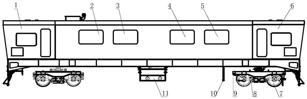
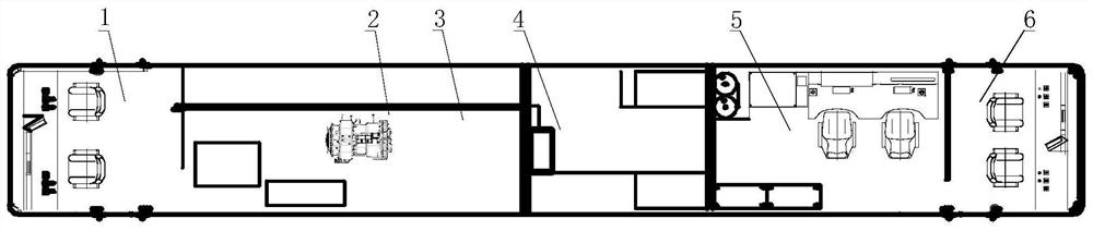
[0047] Embodiment 1.1: The large-scale road maintenance equipment used to detect the loosening of track fasteners includes a vehicle frame, and a running mechanism 7 is arranged below the vehicle frame. The running mechanism 7 includes a braking system 8, and a rail inspection beam is also provided on the running mechanism 7 9. The lower part of the frame includes the fuel tank 11, the upper part of the frame includes the front driver's cab 1 and the rear driver's cab 6, and the space between the front driver's cab 1 and the rear driver's cab 6 includes the power room 2, auxiliary generator 3, electrical system 4 and fasteners The loose detection room 5 includes a high-definition camera 10 in front of the rail inspection beam 9 at the lower part of the vehicle frame.

[0048] The fastener loose detection room 5 includes a laser range finder, a vibration compensation device, a microcomputer control system, a video recognition system and a positioning synchronization system. The ...


PUM


Abstract

The invention provides large-scale road maintenance equipment for detecting looseness of a rail fastener. The equipment comprises a fastener looseness detection device and is characterized in that thefastener looseness detection device comprises a laser range finder, a vibration compensation device, a microcomputer control system, a video recognition system and a positioning synchronization system, the laser range finder is connected with the microcomputer control system, and the microcomputer control system is also connected with the video recognition system, the positioning synchronizationsystem and the vibration compensation device. Laser measurement is adopted, meanwhile, a vibration compensation system is arranged, the vibration compensation device measures vertical acceleration ofa detection beam through an inertia packet in the measurement beam, adverse factors such as gravity components and the like are removed, and secondary integration is carried out on the acceleration toobtain a displacement value. The vibration compensation device can compensate the influence of the vibration displacement of a train without being influenced by the vibration of the train, and a result is more accurate.

Description

technical field [0001] The invention relates to a large-scale road maintenance equipment for identifying loose fasteners for railway and subway rails, and belongs to the technical field of engineering equipment. Background technique [0002] With the rapid development of my country's railway industry, rail transit has become the most important tool for people to travel. Therefore, ensuring the safe, stable and uninterrupted operation of trains has become an important mission of Chinese railway personnel. Reasonable maintenance of railway line equipment and timely and effective analysis, prevention and remediation of line equipment diseases are the keys to ensure safe railway transportation. In the line maintenance, the daily inspection of the fasteners is one of the necessary inspection items. If the railway rail fasteners are loose or damaged, the loosening of a fastener can easily induce the loosening of the surrounding fasteners and aggravate the damage of the track struc...

Claims


Application Information

Patent Timeline
IPC IPC(8): B61K9/08G01S17/08G01M13/00
CPCB61K9/08G01M13/00G01S17/08
Inventor 王园张世璞张宝明高珍
Owner CRCC HIGH TECH EQUIP CORP LTD
Why Eureka
Try Eureka