Living body cold chain transportation equipment

A technology of cold chain transportation and equipment, which is applied in the direction of transportation and packaging, packaging objects under special gas conditions, shock-sensitive objects, etc., and can solve problems such as low water and oxygen content and temperature changes in transportation boxes

Inactive Publication Date: 2021-02-05
西安思明制冷设备工程有限公司
View PDF2 Cites 1 Cited by
  • Summary
  • Abstract
  • Description
  • Claims
  • Application Information

AI Technical Summary

Problems solved by technology

[0007] The purpose of the present invention is to solve the problem in the prior art that the temperature change of the transport box is difficult to affect the fresh food while the water and oxygen content in the transport box is low, and a living cold chain transport equipment is proposed.

Method used


Image

  • Living body cold chain transportation equipment
  • Living body cold chain transportation equipment

Examples


Embodiment 1

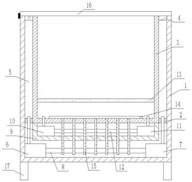
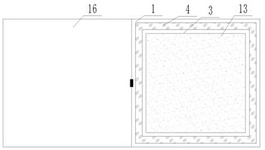
[0023] Example 1 as figure 1 As shown, this living body cold chain transport equipment includes a housing 1, the inner wall of the housing 1 is fixedly connected with a connecting plate 2, the inner wall of the connecting plate 2 is fixedly connected with a transport box 3, and the connecting plate shell 1 and the transport box 3 is fixedly connected with an annular water baffle 4, and an annular water tank 5 is formed between the annular water baffle 4, the transport box 3, the connecting plate 2 and the housing 1, and the annular water tank 5 is filled with cooling water. The inside of the housing 1 The wall is fixedly connected with a cooling water tank 6 and a centrifugal pump 7, and the water outlet of the cooling water tank 6 is fixedly connected to the water inlet of the centrifugal pump 7 through a conduit 8, and the water inlet of the cooling water tank 6 and the water outlet of the centrifugal pump 7 both pass through the side of the connecting plate The wall is fixe...

Embodiment 2

[0024] Embodiment 2 is on the basis of embodiment 1 such as figure 1 As shown, the inner wall of the transport box 3 is fixedly connected with a filter screen 13 , which can reduce impurities from falling into the water inlet of the water oxygen machine 10 .

Embodiment 3

[0025] Embodiment 3 is such as on the basis of embodiment 1 figure 1 As shown, the inner wall of the bottom end of the transport box 3 is fixedly connected with a heat conduction plate 14, and the lower end of the heat conduction plate 14 is fixedly connected with a plurality of heat conduction fins 15 penetrating through the side wall of the transport case 3, and a plurality of heat conduction fins 15 penetrate the side of the U-shaped plate 9 The walls are all sleeved on the tube walls of the conduit 8 and the circulation tube 12, which can facilitate cold and heat exchange and improve the cooling effect.


PUM


Abstract

The invention relates to the technical field of living body cold chains, and discloses living body cold chain transportation equipment. The living body cold chain transportation equipment comprises ashell; the inner side wall of the shell is fixedly connected with a connecting plate; the inner side wall of the connecting plate is fixedly connected with a transportation box; an annular waterproofplate is fixedly connected among the connecting plate, the shell and the transportation box; an annular water tank is formed among the annular waterproof plate, the transportation box, the connectingplate and the shell and filled with cooling water; a refrigerating water tank and a centrifugal pump are fixedly connected to the inner side wall of the shell; a water outlet of the refrigerating water tank is fixedly connected to a water inlet of the centrifugal pump through a guide pipe; a water inlet of the refrigerating water tank and a water outlet of the centrifugal pump both penetrate through the side wall of the connecting plate to be fixedly connected into the annular water tank; and a U-shaped plate is fixedly connected to the lower end of the transportation box. According to the living body cold chain transportation equipment, the temperature maintaining effect of the equipment is improved, the temperature change is reduced, the water oxygen content and the water flow activity are improved, and the equipment is convenient for people to use.

Description

technical field [0001] The invention relates to the technical field of living body cold chain, in particular to a living body cold chain transportation equipment. Background technique [0002] Cold chain transportation refers to the transportation in which the transported goods are kept at a certain temperature during the whole process of transportation, whether it is loading and unloading, changing transportation methods, changing packaging equipment, etc. The cold chain transportation methods can be road transportation, water transportation, Railway transportation, air transportation, or a comprehensive transportation method composed of multiple transportation methods. Cold chain transportation is an important link in cold chain logistics. The cost of cold chain transportation is high, and it includes more complicated mobile refrigeration technology and incubator manufacturing. Technology, cold chain transportation management contains more risks and uncertainties. [0003...

Claims


Application Information

Patent Timeline
Patent Type & Authority Applications(China)
IPC IPC(8): B65D81/18B65D81/20
CPCB65D81/18B65D81/20
Inventor 王凯
Owner 西安思明制冷设备工程有限公司
Why Eureka
Try Eureka