Horizontal directional drilling engineering geological survey wire line coring turbodrill

A rope coring and engineering geology technology, applied in the field of engineering geological survey equipment, can solve problems such as inability to meet, reduce survey efficiency, and heavy workload, and achieve the effect of increasing efficiency

Inactive Publication Date: 2021-02-05
CHINA UNIV OF GEOSCIENCES (WUHAN) +2
View PDF14 Cites 3 Cited by
  • Summary
  • Abstract
  • Description
  • Claims
  • Application Information

AI Technical Summary

Problems solved by technology

[0003] The wireline coring tool in the existing vertical drilling and coring technology consists of a drill pipe, a wireline coring assembly and a drill bit, wherein the wireline coring assembly is installed inside the drill pipe, and the drill bit is installed in the drill pipe. At the end, the mode of "down coring tube-coring-trajectory measurement-controlling deviation correction-bottom coring tube" is adopted for drilling and coring, guiding, and direction-controlling separation, although the efficiency of this method is higher than that of traditional drilling and coring technology, but the drilling tool provides the drilling pressure and torque required by the drill bit by the drill pipe, but the drilling tool needs to be controlled and corrected, which greatly reduces the survey efficiency, and the workload of horizontal drilling survey is larger than that of vertical drilling survey , so the drilling tool cannot meet the technical requirements of horizontal directional drilling engineering geological survey

Method used


Image

  • Horizontal directional drilling engineering geological survey wire line coring turbodrill
  • Horizontal directional drilling engineering geological survey wire line coring turbodrill
  • Horizontal directional drilling engineering geological survey wire line coring turbodrill

Examples


Embodiment Construction

[0016] The present invention will be further described below in conjunction with drawings and embodiments.

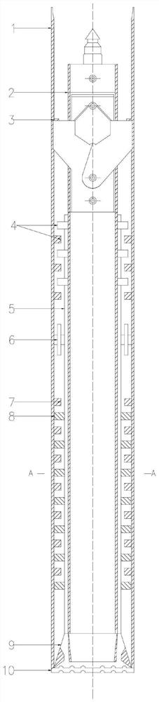
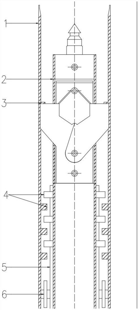
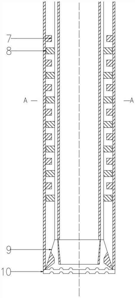
[0017] Such as Figure 1~3 As shown, a wireline coring turbodrill for horizontal directional drilling engineering geological survey includes a drill pipe 1, a wireline coring assembly 2 and a drill bit 10. The wireline coring assembly 2 is located inside the drill pipe 1, The drill bit 10 is located at the end of the drill rod 1, and the drill bit 10 is not directly connected to the drill rod 1. A turbine assembly, a rotating shaft 5 and a support member are arranged between the drill rod 1 and the wireline coring tool assembly 2, wherein the inner wall of the rotating shaft 5 is connected to the The rope core drilling tool assembly 2 is connected, the rotating shaft 5 is connected with the drill bit 10 through the joint 9 and drives the drill bit 10 to rotate through the joint 9, the turbine assembly includes a plurality of stators 7 and a plurality of rotors 8, and on...


PUM


Abstract

The invention discloses a horizontal directional drilling engineering geological survey wire line coring turbodrill, and belongs to the field of engineering geological survey instruments. The wire line coring turbodrill comprises a drill rod, a wire line coring drill assembly, a drill bit, a turbine assembly, a rotating shaft and a support component, wherein the support component is positioned between the drill rod and the rotating shaft to provide radial support, the rotating shaft is connected with the drill bit through a connector instead of directly connecting the drill rod with the drillbit, rotors and stators of the turbine assembly are arranged in the axial direction of the drill rod in a staggered and spaced mode and are arranged in the cross section direction of the drill rod ina spaced mode, so that a slurry channel is formed, slurry enters the slurry channel, drives the rotors to rotate and further drives the rotating shaft connected with the rotors to rotate, furthermore,the rotating shaft drives the drill bit to rotate through the connector, so that the drill bit does not need to be driven by the drill rod to rotate, the drilling tool does not need to be subjected to direction-control deviation-rectifying work, and meanwhile exploration efficiency is improved.

Description

technical field [0001] The present invention relates to a horizontal directional drilling engineering geological survey rope coring turbine drilling tool, which belongs to the field of engineering geological survey equipment. Background technique [0002] Wireline core drilling tool is a drilling tool that does not lift the core, that is, during the drilling process, when the core tube is full or the core is blocked, it is not necessary to lift all the drill strings in the hole to the surface, but by means of The special fishing tool fishes the inner core tube out of the drill string with wire rope and lifts the entire drill pipe only when the drill bit is worn out and needs to be inspected or replaced. [0003] The wireline coring tool in the existing vertical drilling and coring technology consists of a drill pipe, a wireline coring assembly and a drill bit, wherein the wireline coring assembly is installed inside the drill pipe, and the drill bit is installed in the drill...

Claims


Application Information

Patent Timeline
Patent Type & Authority Applications(China)
IPC IPC(8): E21B7/04E21B25/16E21B25/10E21B41/00
CPCE21B7/046E21B25/10E21B25/16E21B41/00
Inventor 舒恒程勇刘夏临陈必光马保松闫雪峰李信杰彭文波史世波杨林松
Owner CHINA UNIV OF GEOSCIENCES (WUHAN)
Why Eureka
Try Eureka