A kind of sprag type overrunning clutch
A technology of overrunning clutch and diagonal brace, which is applied in clutches, one-way clutches, mechanical equipment, etc., to achieve the effect of simple friction resistance structure, convenient processing and manufacturing, and reducing friction resistance.
- Summary
- Abstract
- Description
- Claims
- Application Information
AI Technical Summary
Problems solved by technology
Method used
Image
Examples
specific Embodiment 1
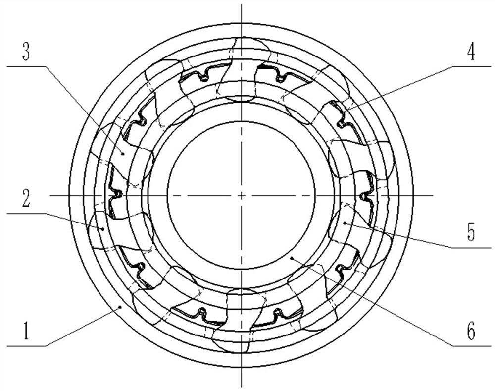
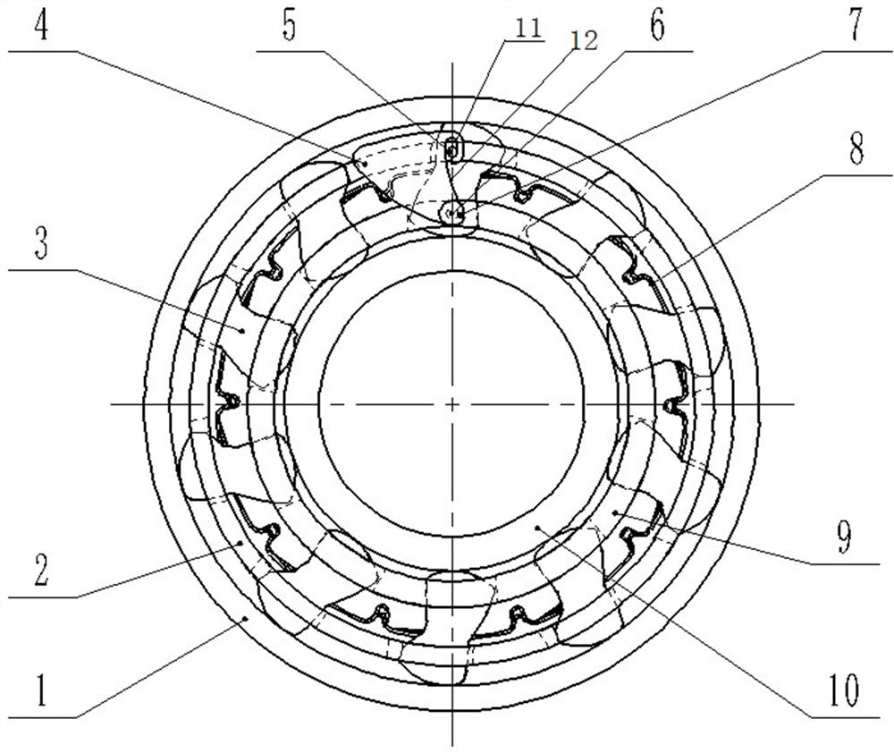
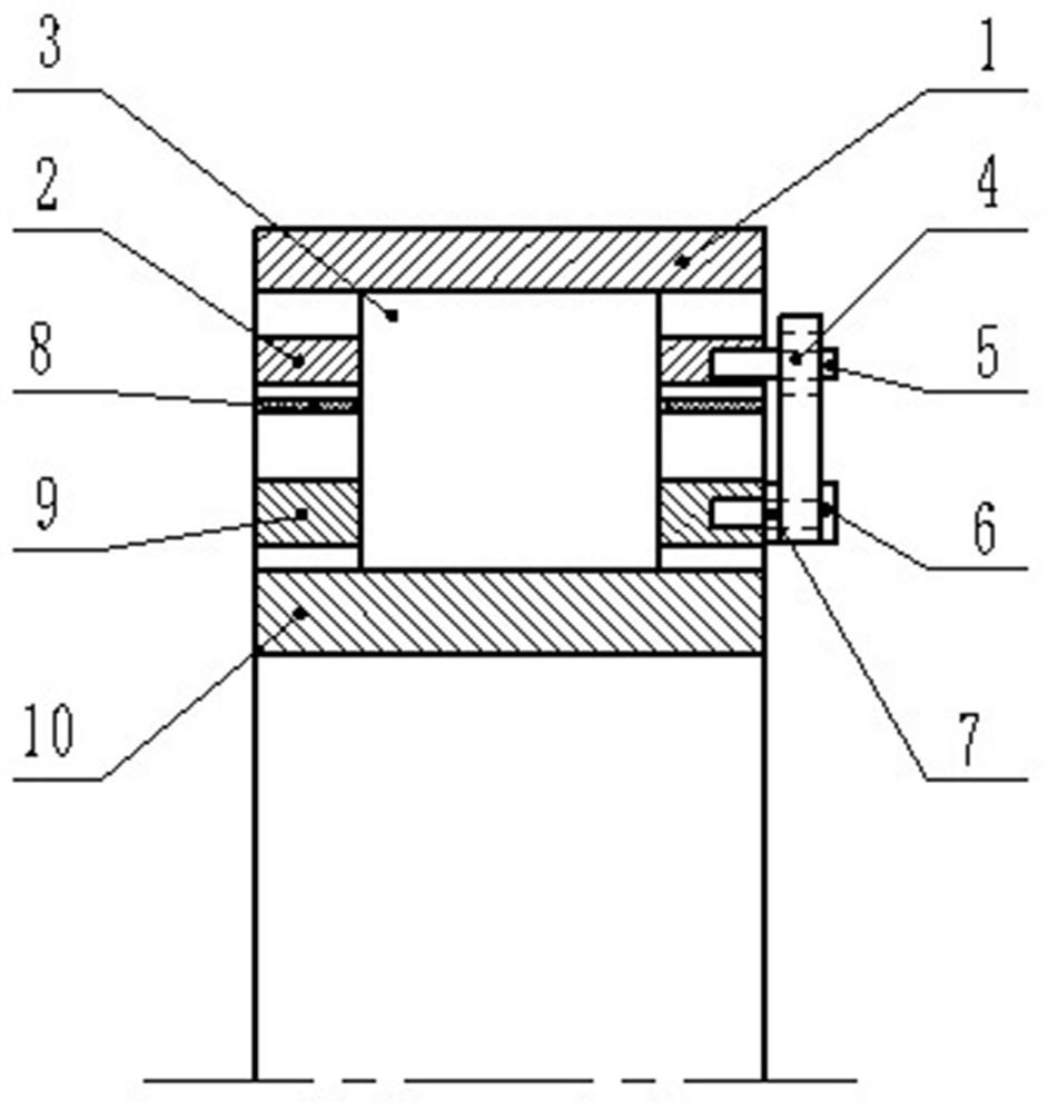
[0047] Such as Figure 2 to Figure 5 As shown, the sprag type overrunning clutch in this embodiment includes an inner ring 10, an inner cage 9, a wave spring 8, an outer cage 2, and an outer ring 1 arranged sequentially from inside to outside. The inner ring 10 and the outer ring 1 There are several wedges 3 arranged in between, and all the wedges 3 are distributed at intervals in sequence along the circumference of the inner ring 10, and all the wedges 3 are correspondingly distributed in the window holes of the inner cage 9, the wave spring 8 and the outer cage 2 Inside, and use the wave spring 8 to apply elastic force to each wedge 3, forcing the wedge 3 to maintain pressure contact with the inner raceway of the inner ring 10 and the outer raceway of the outer ring 1, so as to realize the normal operation beyond the cage.
[0048] In this embodiment, the inner ring 10 is used for transmission connection with the active part. In the state of torque transmission, the wedge bl...
specific Embodiment 2
[0058] The main difference between it and Embodiment 1 is that in Embodiment 1, the position of the center of gravity of the wedge makes the overrunning clutch a centrifugal disengagement type clutch, and the adjustment block can be used to further reduce the wear of the wedge working surface and the inner and outer raceways. In this embodiment, the center position of the wedge makes the overrunning clutch a centrifugal engagement type. In order to transform it into a centrifugal disengagement clutch, an adjustment block is arranged here. Under the action of centrifugal force, the adjustment block drives the inner and outer cages to rotate relative to each other. , forcing the wedge to swing in the direction of disengaging from the two raceways, which can effectively reduce the wear on the working surface of the wedge and the two raceways. The clutch can be successfully rebuilt without replacing the wedge. The structure is simple and easy to use.
specific Embodiment 3
[0060] The difference from Embodiment 1 mainly lies in that the adjustment block is hingedly connected with the inner cage through the hinge shaft, and is connected with the outer cage through the drive structure. In the overrunning state, the adjustment block swings under the centrifugal force. In this embodiment, the adjustment block is hingedly connected to the outer cage through the hinge shaft, and is connected to the outer cage through the drive structure. It is only necessary to ensure that the center of gravity of the adjustment block is located at the set side according to the actual working needs of the clutch. Here, The setting side refers to meeting the following requirements: when the sprag type overrunning clutch is in the overrunning condition, the adjustment block swings around the hinge shaft by the centrifugal force, and the two cages are driven to rotate relative to each other through the driving structure, and then all the wedges are driven to disengage synch...
PUM
 Abstract
Description
Claims
Application Information
 - R&D
- Intellectual Property
- Life Sciences
- Materials
- Tech Scout
- Unparalleled Data Quality
- Higher Quality Content
- 60% Fewer Hallucinations
Browse by: Latest US Patents, China's latest patents, Technical Efficacy Thesaurus, Application Domain, Technology Topic, Popular Technical Reports.
© 2025 PatSnap. All rights reserved.Legal|Privacy policy|Modern Slavery Act Transparency Statement|Sitemap|About US| Contact US: help@patsnap.com


