Water level sensor

A water level sensor and intermediate position technology, applied in the field of sensors, can solve the problems of low flexibility in sensor disassembly and assembly, the inability of the water level sensor to ensure the level of the detection surface, and the non-adjustable wiring tightness, etc., to achieve good sealing, The effect of avoiding short circuit and improving sealing effect

Inactive Publication Date: 2021-02-05
JIAXING UNIV
View PDF0 Cites 2 Cited by
  • Summary
  • Abstract
  • Description
  • Claims
  • Application Information

AI Technical Summary

Problems solved by technology

[0004] A water level sensor proposed by the present invention solves the problems that the water level sensor cannot ensure the level of the detection surface, the structure has poor sealing performance, the installation of terminals is inconvenient, the tightness of wiring cannot be adjusted, and the flexibility of disassembly and assembly of the sensor and the accuracy of assembly are low.

Method used


Image

  • Water level sensor
  • Water level sensor
  • Water level sensor

Examples


Embodiment 1

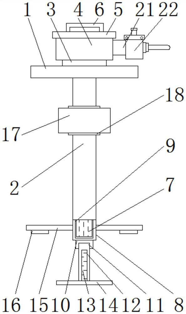
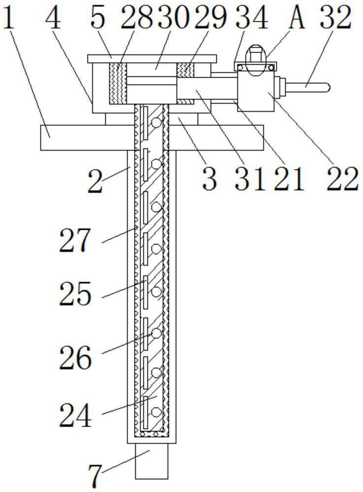
[0031] refer to Figure 1-6, a water level sensor, comprising a base plate 1, a sleeve rod 2 is vertically welded between the middle positions of the upper and lower surfaces of the base plate 1, a gasket 3 is fixedly installed at the middle position of the upper surface of the base plate 1, and the upper surface of the gasket 3 is welded with a fixed Block 4, the lower surface of the sleeve rod 2 is welded with a clamp column 7, and the sleeve rod 2 is movably installed with a column sleeve 8 through the clamp column 7, and the lower surface of the column sleeve 8 is welded with an inner threaded sleeve 10, and the column sleeve 8 passes through the inner screw The sleeve 10 is movably connected with a support rod 11, and a bump 21 is welded on one side of the outer wall of the fixed block 4, and the side wall of the bump 21 away from the fixed block 4 is fixedly installed with a wiring cover 22, and the wiring cover 22 is far away from the bump 21 Three sets of wire sleeves ...

Embodiment 2

[0034] refer to Figure 2-7 , a water level sensor, comprising a base plate 1, a sleeve rod 2 is vertically welded between the middle positions of the upper and lower surfaces of the base plate 1, a gasket 3 is fixedly installed at the middle position of the upper surface of the base plate 1, and the upper surface of the gasket 3 is welded with a fixed Block 4, the lower surface of the sleeve rod 2 is welded with a clamp column 7, and the sleeve rod 2 is movably installed with a column sleeve 8 through the clamp column 7, and the lower surface of the column sleeve 8 is welded with an inner threaded sleeve 10, and the column sleeve 8 passes through the inner screw The sleeve 10 is movably connected with a support rod 11, and a bump 21 is welded on one side of the outer wall of the fixed block 4, and the side wall of the bump 21 away from the fixed block 4 is fixedly installed with a wiring cover 22, and the wiring cover 22 is far away from the bump 21 Three sets of wire sleeves...


PUM


Abstract

The invention belongs to the field of sensors, particularly relates to a water level sensor, and aims to solve the problems that an existing water level sensor cannot guarantee the levelness of a detection surface, is poor in structure sealing performance, inconvenient in terminal installation, unadjustable in wiring tightness and low in sensor disassembly and assembly flexibility and assembly precision. The invention provides the following scheme that the water level sensor comprises a base plate. A sleeve rod is vertically welded between the middle positions of the upper surface and the lower surface of the base plate, a gasket is fixedly installed in the middle position of the upper surface of the base plate, a fixing block is welded to the upper surface of the gasket, a clamping columnis welded to the lower surface of the sleeve rod, a column sleeve is movably installed on the sleeve rod through the clamping column, and an inner threaded sleeve is welded to the lower surface of the column sleeve. According to the invention, the water level sensor can guarantee the level of the detection surface to improve the accuracy of water level detection, the sealing performance of the structure is good, the terminals are convenient to install in the wiring area and can be adjusted in tightness, and the disassembly and assembly flexibility and assembly accuracy of the sensor are high.

Description

technical field [0001] The invention relates to the field of sensors, in particular to a water level sensor. Background technique [0002] The water level sensor moves vertically along the sleeve rod based on the buoyancy of the floating ball. When the magnet in the floating ball interacts with the reed switch at the corresponding height, the reed switch closes to change the resistance value of the series circuit and adjust the output voltage. It is widely used to detect water level. [0003] When the existing water level sensor is in use, it cannot be placed vertically, resulting in being unable to keep perpendicular to the highest surface of the water level and affecting the accuracy of water level detection. The poor sealing of the structure makes the internal circuit structure easy to be damp and short-circuited, which affects the water level detection. The smooth progress of the terminal installation in the wiring area is inconvenient and cannot be adjusted tightly, re...

Claims


Application Information

Patent Timeline
Patent Type & Authority Applications(China)
IPC IPC(8): G01F23/72
CPCG01F23/72
Inventor 赵浩李洪武周丽许聚武王挺丁立军陈晟习聪玲
Owner JIAXING UNIV
Why Eureka
Try Eureka