
Defect detection system based on space step-by-step frequency shift illumination
A defect detection, step-by-step technology, used in optical testing flaws/defects, measuring devices, analyzing materials, etc., which can solve the problem of large incident light divergence angle, reduced accuracy of sub-aperture spectral information, and surface microscopic observation of non-transparent samples. Inapplicability and other problems, to avoid missed detection and false detection, and improve the effect of spatial bandwidth product
- Summary
- Abstract
- Description
- Claims
- Application Information
AI Technical Summary
Problems solved by technology
Method used
Image


Examples
Embodiment Construction
[0023]The technical scheme of the invention will be further described below in conjunction with the drawings and specific embodiments.
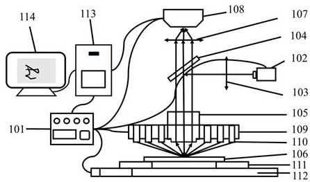
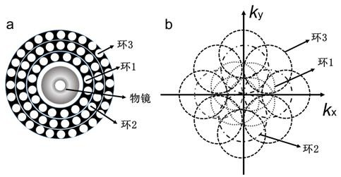
[0024]Such asfigure 1 As shown, the defect detection system based on the spatially stepped frequency shifted illumination of the present invention mainly includes a light source, a microscope objective lens 105, a tube lens 107, an image detector 108, a control module 101 and a data processing module 113. Among them, the light source includes a vertical lighting source 102 and an inclined lighting unit 110. The inclined lighting unit 110 may choose to use light sources such as LED light sources, LD light sources, and fiber bundle output light sources. Preferably, an optical collimating device can be provided at the exit port of the vertical illumination light source and each inclined illumination unit to project the emitted light into the imaging field of view of the optical microscope objective lens 105 to improve the direction collimation of the ill...
PUM
 Abstract
Description
Claims
Application Information