
Flat plate type laser beam splitting film based on composite material and design method of flat plate type laser beam splitting film

A technology of composite materials and design methods, which is applied in optics, optical components, instruments, etc., can solve problems such as increasing the difficulty of film thickness, and achieve the effect of increasing laser damage threshold, high refractive index, and reducing film thickness monitoring.

Active Publication Date: 2021-02-05
SHANGHAI INST OF OPTICS & FINE MECHANICS CHINESE ACAD OF SCI
View PDF7 Cites 0 Cited by
  • Summary
  • Abstract
  • Description
  • Claims
  • Application Information

AI Technical Summary

Problems solved by technology

Due to the limited coating materials available in nature, in order to achieve a specific transmittance (the ratio of the transmitted beam intensity T to the reflected beam intensity R), it is often necessary to design an irregular film structure, which increases the difficulty of film thickness control

Method used


Image

  • Flat plate type laser beam splitting film based on composite material and design method of flat plate type laser beam splitting film
  • Flat plate type laser beam splitting film based on composite material and design method of flat plate type laser beam splitting film
  • Flat plate type laser beam splitting film based on composite material and design method of flat plate type laser beam splitting film

Examples


Embodiment Construction

[0041]The present invention will be further described below in conjunction with the embodiments and drawings.

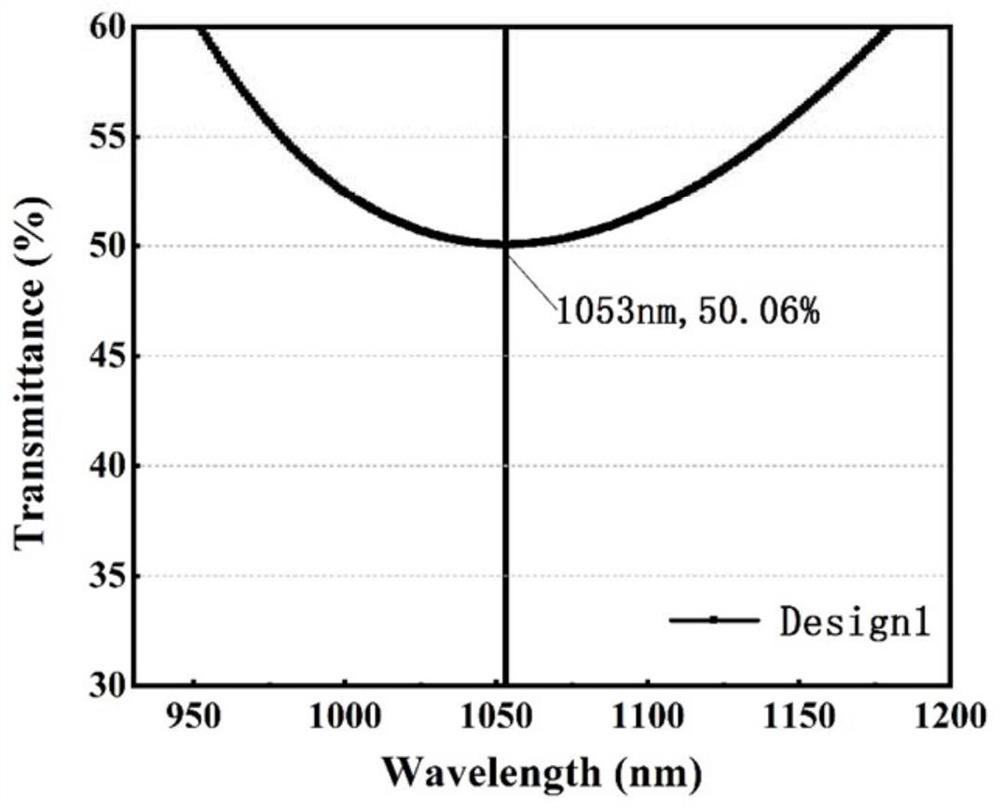
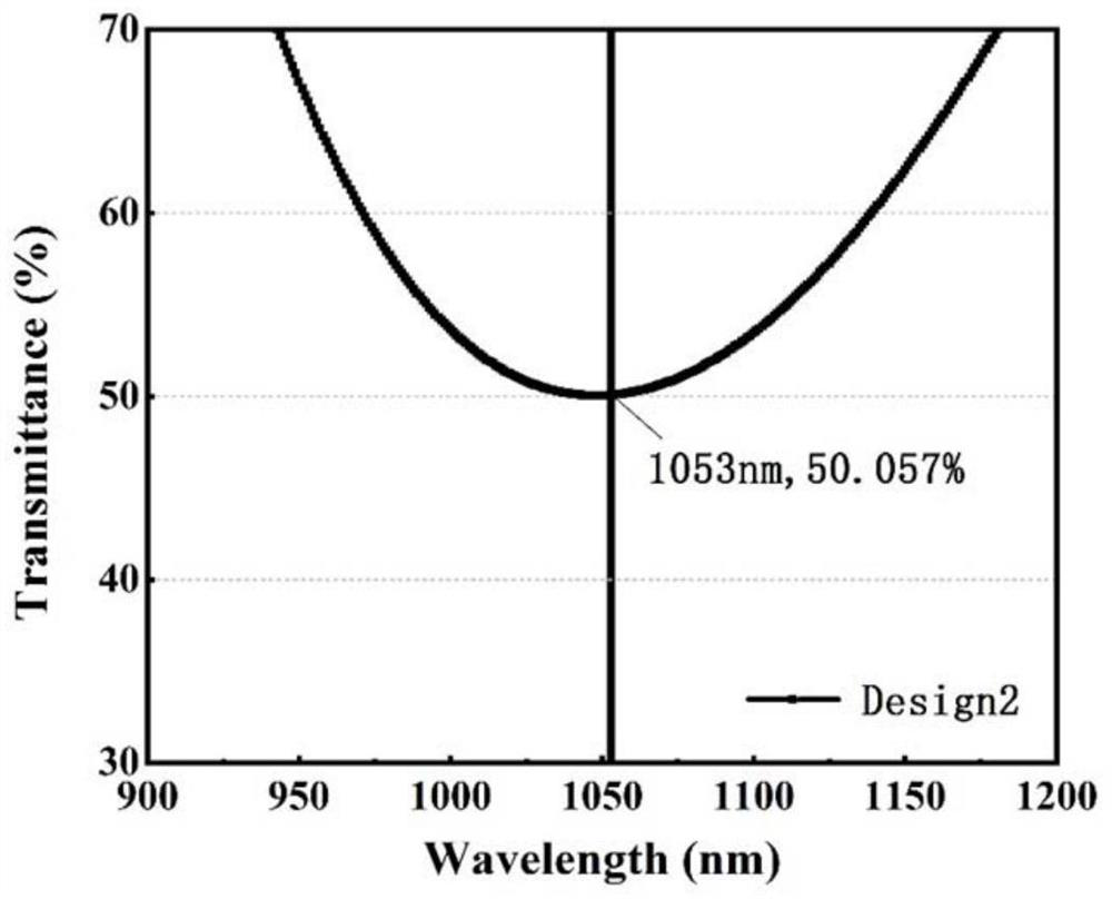
[0042]Taking a 45-degree incident, s-polarization component, and achieving a transmittance of 50±1% at 1053 nm as an example, a flat-plate laser beam splitting film based on a composite material and a design method thereof are described in the present invention.

[0043]The design method specifically includes the following steps:

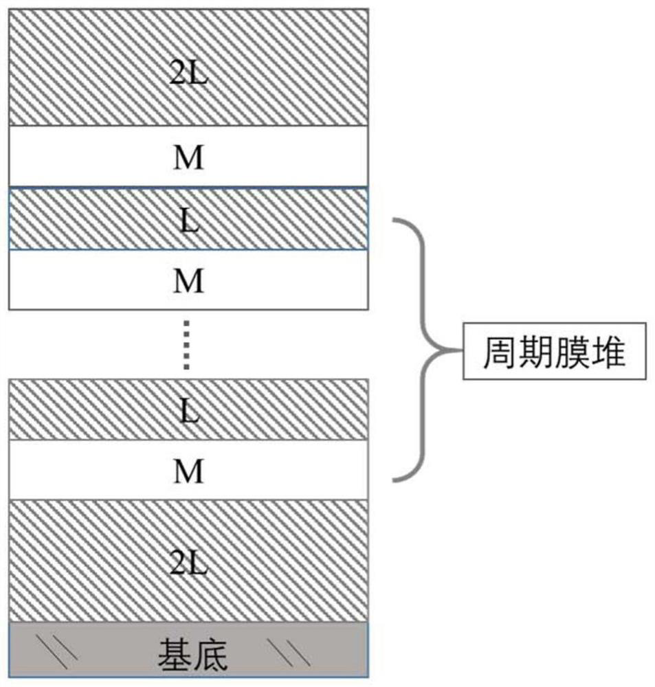
[0044]1) Parameter setting: design transmittance value T of laser beam splitting filmD=50%, beam incident angle θ=45°, incident beam is s-polarized component, at the center wavelength of 1053nm, the refractive index of the quartz substrate is nS= 1.4378, HfO2Refractive index of material nA= 1.9088, Al2O3Refractive index of material nB= 1.5910, SiO2Refractive index of material nC=1.4212, the initial film structure is S|dL(HL)gHmL|A, where S represents a substrate, H represents a high refractive index film with an optical thickness of λ / 4 (λ refers to the ...


PUM

PropertyMeasurementUnit
optical band gapaaaaaaaaaa
refractive indexaaaaaaaaaa

Abstract

The invention relates to a flat plate type laser beam splitting film based on a composite material and a design method of the flat plate type laser beam splitting film. Based on a given regular film system structure, a single material A with the refractive index greater than 1.8, a single material B with the optical band gap greater than 6.0 eV and a single low-refractive-index material C are usedfor designing the laser beam splitting film, the film layer cycle numbers a and b in the film system structure required to achieve the target transmittance are calculated, and then the value range (a<g<b) of the film cycle number g when the laser beam splitting film is designed by a composite material M composed of the material A and the material B and the single low-refractive-index material C,and the film system structure parameters required for realizing the target transmittance are calculated. According to the invention, the refractive index regulation advantage of the composite materialis utilized, and the beam splitting film with a regular film system structure is designed according to the target transmittance, so that the requirement on film thickness monitoring is reduced; and due to the use of the composite material M, the electric field distribution in the film layer can be reduced, the respective advantages of the material A and the material B are fully utilized, and thelaser damage threshold of the beam splitting film is improved.

Description

Technical field[0001]The invention relates to the technical field of optical thin films, and relates to a flat-plate laser beam splitting film based on composite materials and a design method thereof.Background technique[0002]The beam splitter is used to separate incident light into reflected light and transmitted light. It is widely used in various optical systems and is an important component of optical research and use systems. Commonly used beam splitters have two structures: one is to deposit a thin film on a transparent flat plate to form a flat beam splitter; the other is to coat the film on a 45° right-angle prism slope, and then glue the same Shaped prisms form a cemented cube beam splitter.[0003]The flat beam splitter has the advantages of easy preparation and large size, low cost, flexible design and production, etc., and is widely used in laser systems, especially large laser devices. The ideal laser beam splitting film not only requires that the incident light with a sp...

Claims


Application Information

Patent Timeline
Patent Type & Authority Applications(China)
IPC IPC(8): G02B1/11G02B27/00G02B27/28
CPCG02B1/11G02B27/0012G02B27/283
Inventor 朱美萍杜文云李静平赵泽成刘天宝易葵邵建达
Owner SHANGHAI INST OF OPTICS & FINE MECHANICS CHINESE ACAD OF SCI
Learn More