Continuous structure dynamic load interval identification method

A technology of dynamic load and identification method, applied in the aerospace field, can solve problems such as monotony, and achieve the effect of strong generalization ability, low requirements, and low storage requirements

Active Publication Date: 2021-02-05
BEIHANG UNIV
View PDF6 Cites 1 Cited by
  • Summary
  • Abstract
  • Description
  • Claims
  • Application Information

AI Technical Summary

Problems solved by technology

The current interval uncertainty propagation analysis methods mainly include vertex combination method, perturbation method, and method based on Taylor series expansion, but these methods are suitable for relatively simple problems such as monotone problems, small uncertainty problems and linear problems.

Method used


Image

  • Continuous structure dynamic load interval identification method
  • Continuous structure dynamic load interval identification method
  • Continuous structure dynamic load interval identification method

Examples


Embodiment 1

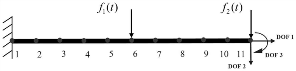
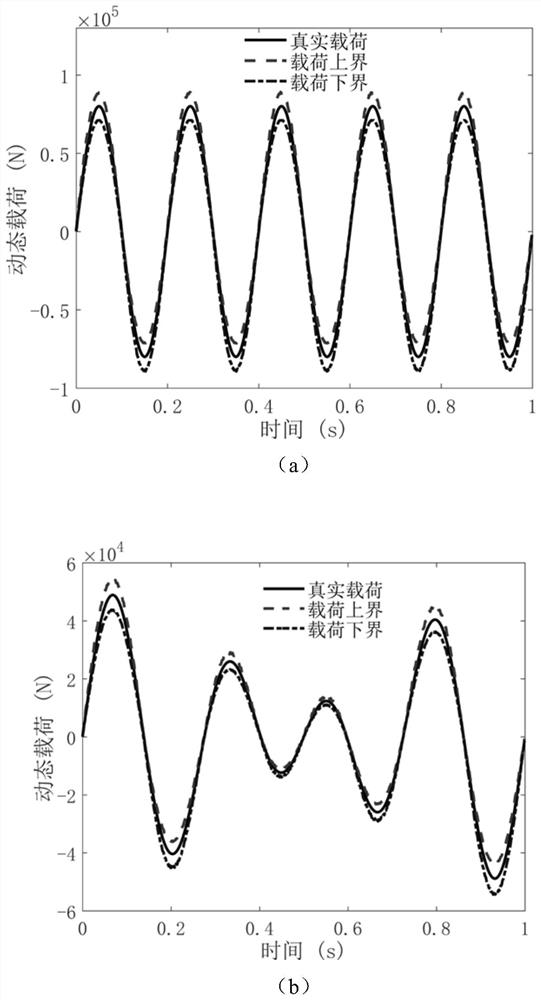
[0094] The aircraft body structure can be simplified as a continuous beam structure, and the finite element model of the continuous beam structure is as follows: figure 2 As shown, the geometric dimensions and material parameters of the continuous beam are shown in Table 1, where the density and elastic modulus are regarded as interval uncertain parameters. The continuous beam structure is divided into 10 Euler beam elements with a total of 11 nodes, and each node has 3 directional degrees of freedom. The first node of the continuous beam structure is fixed, and a vertical dynamic load is applied to the 6th and 11th nodes respectively, and the expressions are f 1 (t)=80000sin(10πt), f 2 (t)=20000sin(6πt)+30000sin(8πt), the load identification process is 1s, and the response measurement frequency is 1000Hz. Sampling is carried out in the space of 1.5 times the interval uncertainty domain, that is, the sampling interval of density is [6630,8970]kg / m 3 , the sampling interval...

Embodiment 2

[0098] The wing and rudder structure of the aircraft can be simplified as a continuous plate structure, and the finite element model of the continuous plate structure is as follows: Figure 4 shown. Among them, the density and elastic modulus are regarded as interval uncertain parameters, and the interval uncertainty domains are [850,1150] kg / m 3 and [178.5, 241.5] GPa. The continuous plate structure is divided into 12 units with a total of 20 nodes, and each node has 6 directional degrees of freedom. The first to fifth nodes of the continuous beam structure are fixed, and a vertical dynamic load is applied to the 13th node. The expressions are f(t)=900000sin(6πt)+500000sin(10πt), and the load identification process is 2s, the response measurement frequency is 1000Hz. The sampling interval of density uncertain variable is [800,1200]kg / m 3 , the sampling interval of the elastic modulus uncertain variable is [168,252]GPa. The sampling size of the Latin hypercube is 200, and...


PUM


Abstract

The invention discloses a continuous structure dynamic load interval identification method, which aims at a continuous structure with interval uncertainty and utilizes limited displacement response and sample information to identify an interval boundary of a dynamic load. The method comprises the following steps: firstly, establishing a finite element model with a continuous structure, convertingthe finite element model into a state space, and randomly generating a plurality of sample points in a sampling space by adopting a Latin hypercube sampling method; at each sample point, on the basisof minimum variance unbiased estimation, achieving one-step delay load identification by utilizing a structure state estimation value and structure observation information, and further achieving stateestimation and further updating of a state estimation covariance matrix under a Kalman filtering framework; and at each sampling moment, based on the uncertain variable uncertain dynamic load sampleset, establishing a random forest proxy model of the load on the interval convex model, and realizing identification of the load interval boundary by searching the maximum value of the proxy model onthe interval uncertain domain.

Description

technical field [0001] The invention relates to the field of aerospace, in particular to a dynamic load interval identification method for a continuous structure. Background technique [0002] In engineering practice, in order to accurately grasp the vibration state of the aircraft, it is often necessary to obtain the external excitation information acting on the structure. However, acquiring load information directly through force sensors is often not feasible due to the high cost and difficulty of installation. In recent years, more and more attention has been paid to the inverse load identification method based on structural vibration response data (displacement, acceleration, strain, etc.) combined with structural system characteristics (mass, stiffness, and mode). Different from directly solving the structural dynamics forward problem of the quadratic differential equation, the inversion process of load identification is often accompanied by many ill-posed problems, re...

Claims


Application Information

Patent Timeline
Patent Type & Authority Applications(China)
IPC IPC(8): G06F30/23G06F30/15G06F30/27G06Q10/04G06K9/62
CPCG06F30/23G06F30/15G06F30/27G06Q10/04G06F18/214
Inventor 王磊刘亚儒李泽商蒋晓航
Owner BEIHANG UNIV
Why Eureka
Try Eureka