
Battery module

A battery module and battery technology, applied in the direction of batteries, battery pack components, secondary batteries, etc., can solve the problem that the width and thickness of the connecting piece cannot be made large, the connecting piece exceeds the temperature inside the battery, and affects the discharge of the module. Power and other issues, to avoid early power limitation, optimize structure and performance, and shorten the temperature transfer path

Active Publication Date: 2021-02-05
CONTEMPORARY AMPEREX TECH CO
View PDF4 Cites 1 Cited by
  • Summary
  • Abstract
  • Description
  • Claims
  • Application Information

AI Technical Summary

Problems solved by technology

[0005] The inventors have found that there are at least the following problems in the prior art: due to the limitation of the space size in the battery module, and considering the influence of manufacturing and cost, the width and thickness of the connecting piece cannot be made very large. Such as 1C discharge, the temperature of the connecting piece is close to the temperature inside the battery, but if a higher discharge rate is used, the temperature of the connecting piece is far higher than the temperature inside the battery
Under high-power working conditions, due to the limitation of the over-current area of ​​the connecting piece, the temperature of the connecting piece will rise sharply, while the temperature inside the battery will rise slowly, and the temperature difference is huge, which leads to the power limit of the battery module in advance, which affects The discharge power of the module

Method used


Image

  • Battery module
  • Battery module
  • Battery module

Examples


Embodiment Construction

[0044] Combine below Figure 1 to Figure 17 The technical solution provided by the present invention is described in more detail.

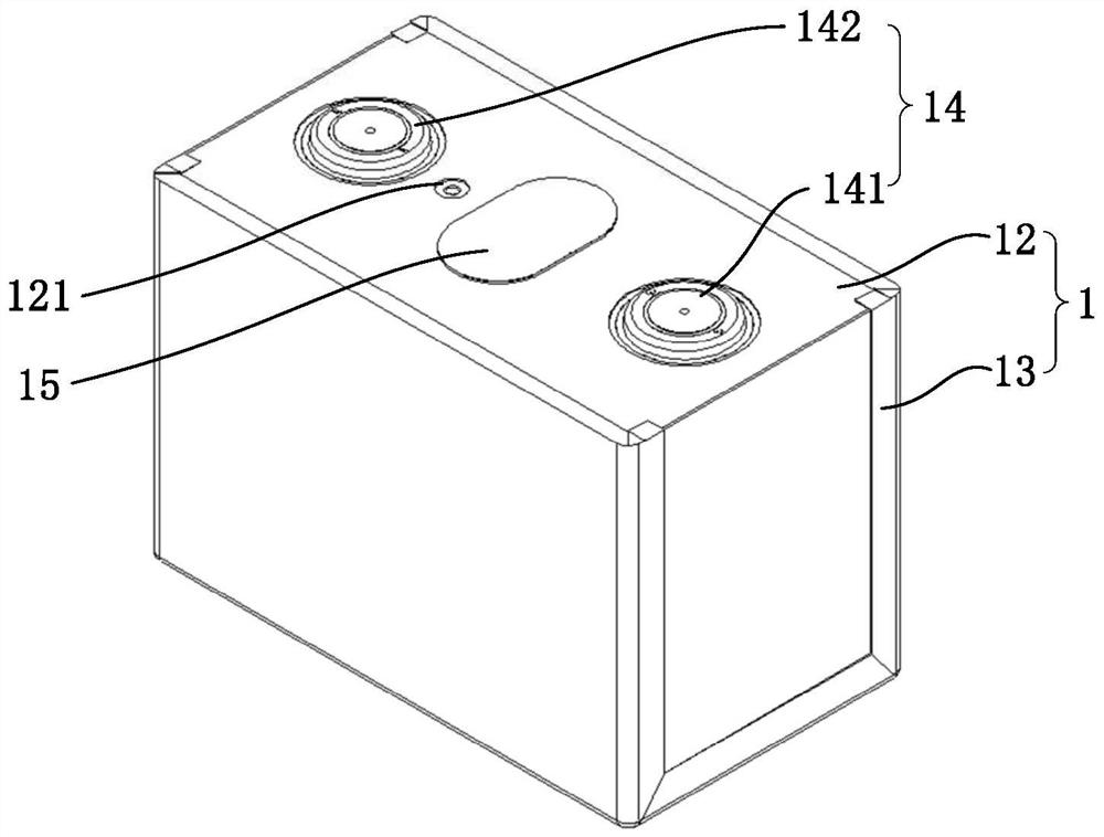
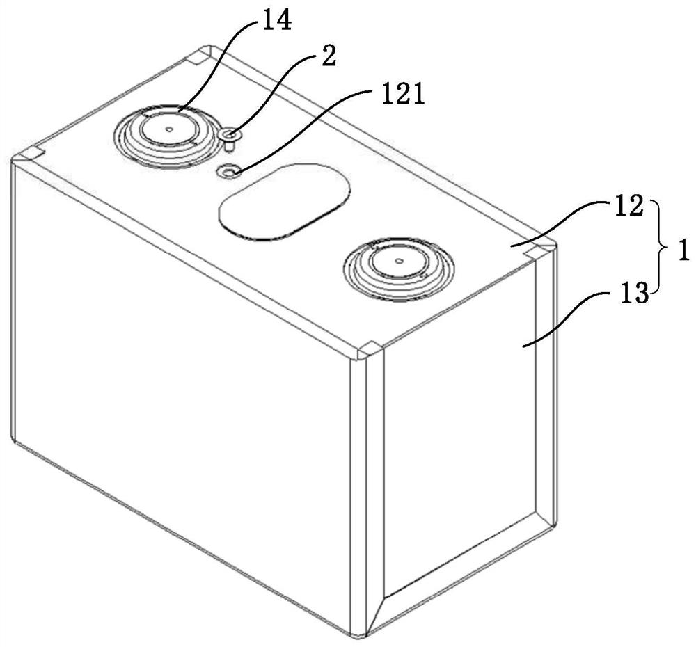
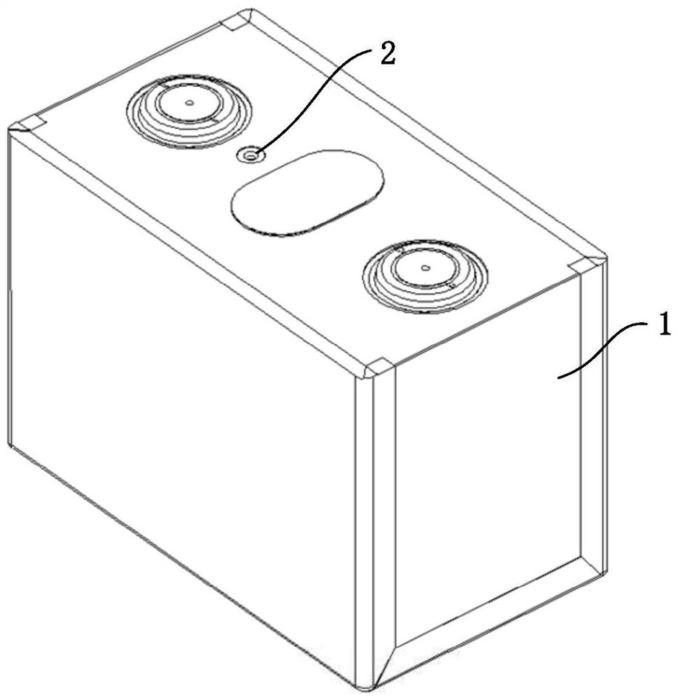
[0045] see Figure 1 to Figure 5 , the embodiment of the present invention provides a battery module, including a battery 1 , a blocking member 2 and a heating component 3 . The battery 1 includes a casing 13 and a cover plate 12 connected to the casing 13 , and the cover plate 12 is provided with a temperature collecting hole 121 . The temperature collection hole 121 is, for example, a through hole, which can realize temperature collection on the one hand, and can also be used to inject electrolyte into the battery 1 . The blocking member 2 includes an insertion portion 21 which is installed in the temperature collection hole 121 and is used to block the temperature collection hole 121 ; The temperature collection component 3 includes a temperature collection part 31 installed inside the accommodating cavity 211 .

[0046] The optional struct...


PUM


Abstract

The invention discloses a battery module, relates to the field of batteries, and is used for optimizing the structure of the battery module. The battery module comprises a battery, a blocking part anda temperature collection assembly. The battery comprises a shell and a cover plate connected with the shell, and the cover plate is provided with a temperature collection hole. The blocking part comprises an insertion part, and the insertion part is mounted in the temperature collection hole; the insertion part is provided with a containing cavity extending into the shell. The temperature collection assembly comprises a temperature collection part, and the temperature collection part is installed in the containing cavity. According to the technical scheme, the temperature collection assemblycollects temperature from the interior of the shell, temperature collection is more accurate, the heat conduction path is short, and the temperature collection response speed is high.

Description

technical field [0001] The invention relates to the field of batteries, in particular to a battery module. Background technique [0002] The normal working temperature of the battery module is between -30°C and 55°C. If the limit temperature is exceeded, the battery module will limit the power to realize the safety protection of the battery module. [0003] The existing temperature collection method of the battery module is as follows: collect the temperature on the connecting piece through the thermistor set on the circuit board, and use the temperature of the connecting piece as the internal temperature of the battery. In actual situations, the temperature on the connection plate is high, while the temperature inside the battery is low. If the difference between the two is large, the battery module will limit the power in advance, which affects the performance of the battery module. [0004] At present, all OEMs in the industry are developing towards the coupe type, and t...

Claims


Application Information

Patent Timeline
Patent Type & Authority Applications(China)
IPC IPC(8): H01M10/48G01K1/14G01K7/22
CPCH01M10/486G01K7/22G01K1/143H01M2220/20G01K1/14G01K2205/00H01M10/425H01M50/15H01M50/176H01M50/209H01M50/572H01M50/287H01M50/103H01M50/184H01M50/186H01M50/55H01M50/249H01M2200/10Y02E60/10B60L50/64B60L58/24H01M10/4207H01M2010/4271
Inventor 曹根姚己华
Owner CONTEMPORARY AMPEREX TECH CO
Learn More