

Detachable wire clamp for live-line lead connection operation
A detachable and lead wire technology, applied in the field of electric power, can solve the problems of small adaptability, small current flow, and it is not easy to confirm the clamping condition of the wire clip on the wire, etc., and achieves the effect of good connection performance and wide application range.
- Summary
- Abstract
- Description
- Claims
- Application Information
AI Technical Summary
Problems solved by technology
Method used
Image

Examples
Embodiment 1
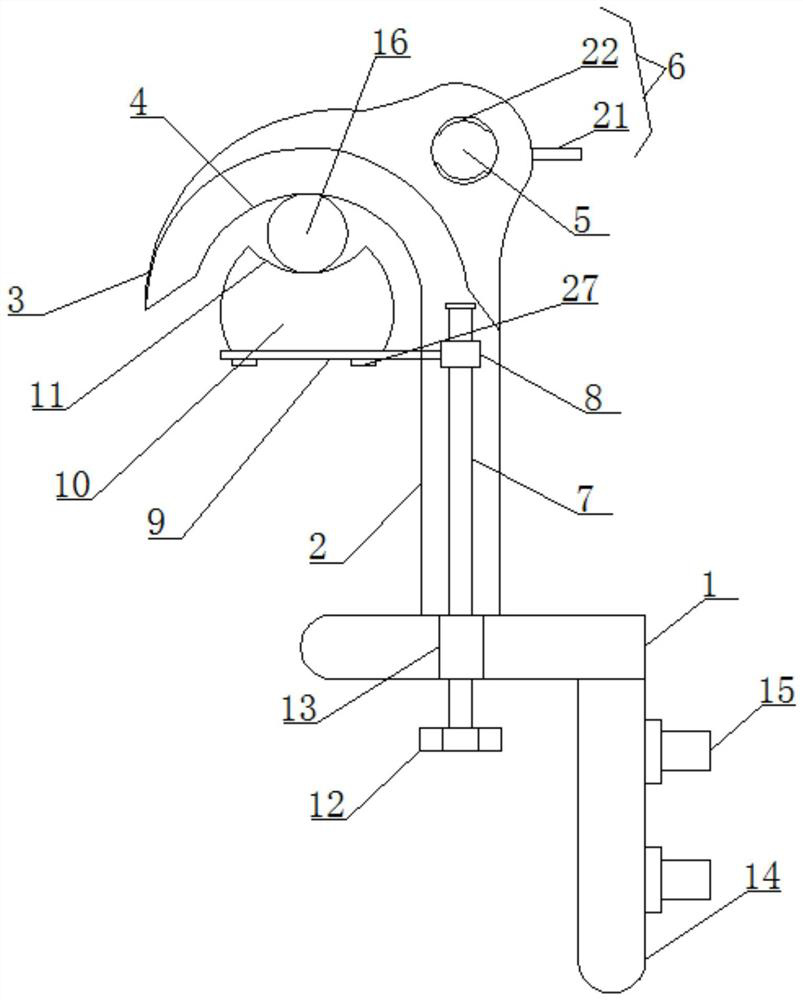
[0024] Such as Figure 1-2 As shown, according to the embodiment of the present invention, the detachable wire clamp for live wire connection operation includes a base plate 1 and a column 2 vertically arranged at the top of the base plate 1. The top of the column 2 is provided with an arc-shaped plate 3 , the bottom end of the arc-shaped plate 3 is provided with an arc-shaped groove 4, and a hole 5 is opened on one side of the arc-shaped plate 3, and a clamping mechanism 6 matching it is provided in the hole 5, and the Column 2 is cavity structure, and described column 2 is provided with vertical screw mandrel 7, and described screw mandrel 7 is set with sliding block 8 matched with it, and one side of described sliding block 8 is provided with The horizontal plate 9 extending to the outside of the column 2 and located below the arc-shaped groove 4, the top of the horizontal plate 9 is provided with a pressing block 10 matching the arc-shaped groove 4, and the pressing block ...
Embodiment 2
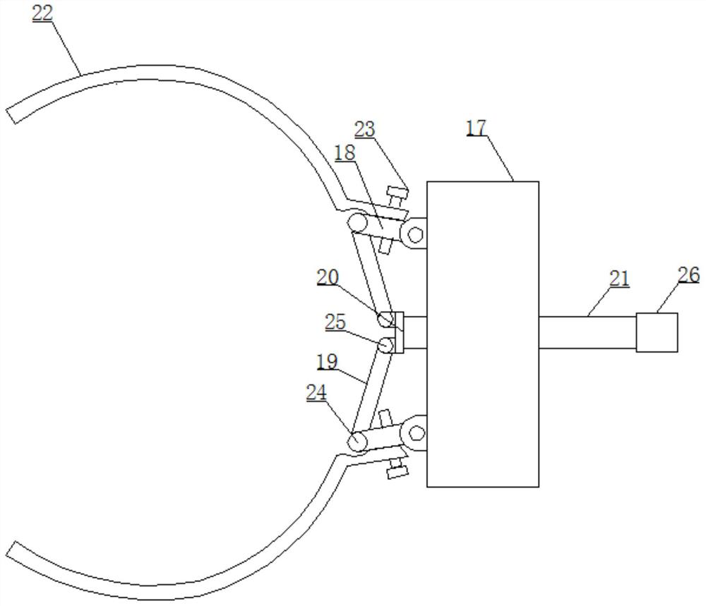
[0026] Such as Figure 1-2 As shown, the clamping mechanism 6 includes a fixed block 17 located in the arc-shaped plate 3, one side of the fixed block 17 is symmetrically provided with an inclined movable rod 18, and one end of the movable rod 18 is close to each other All are equipped with inclined push rods 19, one side of the push rods 19 is provided with a push plate 20, and one side of the push plate 20 is provided with a The outer threaded rod 21, the ends of the movable rods 18 that are far away from each other are provided with a clip 22, the clip 22 is a semicircular structure, and the clip 22 is connected with the movable rod 18 by a bolt 23 , the movable rod 18 is respectively connected with the fixed block 17 and the push rod 19 through the first connecting shaft 24 . It is not difficult to see from the above design that through the design of the clamping mechanism 6, the insulating operating rod can be clamped and fixed, and the push plate 20 is pulled to move to...
Embodiment 3
[0028] Such as Figure 1-2 As shown, the push rod 19 is connected with the push plate 20 through the connecting shaft 25, and the push plate 20 is connected with the threaded rod 21 through the rotating shaft, and the bottom end of the threaded rod 21 is provided with a knob 26. The knob 26 is covered with a matching anti-slip sleeve, and the anti-slip sleeve is made of rubber. It is not difficult to find out from above-mentioned design, the design of connecting shaft 2 25 makes the rotation of push rod 19 more flexible.
PUM
 Abstract
Description
Claims
Application Information