
Self-powered monitoring rolling bearing

A rolling bearing, self-powered technology, applied in the direction of generator/motor, piezoelectric effect/electrostrictive or magnetostrictive motor, engine, etc., can solve the problem that it is difficult to obtain the running state of the bearing in time and accurately, and the battery power supply time is short , stress concentration of equipment parts and other issues, to achieve the effect of simple structure and excitation process, no electromagnetic interference, and effective frequency bandwidth

Active Publication Date: 2021-02-05
ZHEJIANG NORMAL UNIVERSITY
View PDF8 Cites 1 Cited by
  • Summary
  • Abstract
  • Description
  • Claims
  • Application Information

AI Technical Summary

Problems solved by technology

In recent years, people have successively proposed different forms of embedded bearing monitoring systems, which have better solved the problem of measurement accuracy and accuracy, but the structure of related equipment needs to be changed in order to install the sensor monitoring system, which not only easily causes damage to equipment parts. Problems such as stress concentration cannot be realized on some equipment with complex structure or limited space; the most critical thing is that when the monitoring system needs to rotate with the inner and outer rings of the bearing, it is inconvenient to supply power through wires, and the use of battery power supply is very short.
Therefore, the existing bearing monitoring system is basically a regular and indirect non-contact measurement, and it is difficult to obtain the running status of the bearing in a timely and accurate manner.
In view of this, various forms of self-monitoring bearings based on magnetic coupling excitation power generation and power supply have been proposed. The biggest problems are: the existence of magnetic interference, large differences in power generation performance at different speeds, narrow effective frequency bands, and low reliability.

Method used


Image

  • Self-powered monitoring rolling bearing
  • Self-powered monitoring rolling bearing
  • Self-powered monitoring rolling bearing

Examples


Embodiment Construction

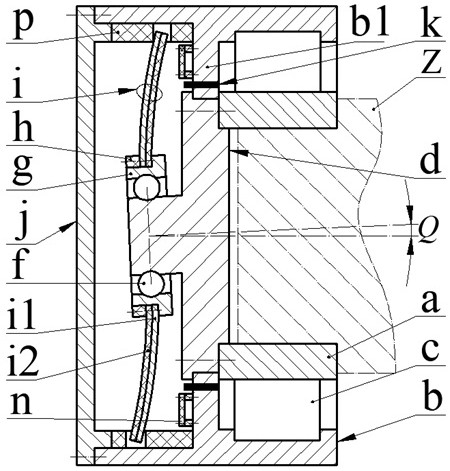
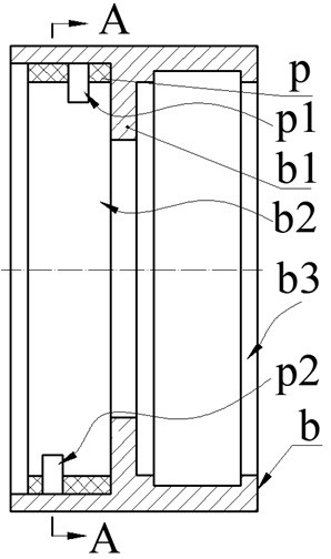
[0020] The present invention proposes a self-powered monitoring rolling bearing, including an inner ring a, an outer ring b, a rolling body c, a pendulum shaft d, a rolling body two f, a pendulum ring g, a pressure ring h, a piezoelectric vibrator i, and an end cover j , sensor k, circuit board n and positioning ring p; the partition b1 on the inner wall of the outer ring b divides the inner cavity of the outer ring b into a left cavity b2 and a right cavity b3; the circuit board n and the sensor are installed on the partition b1 k, the circuit board n is placed in the left cavity b2; the end of the left cavity b2 is installed with an end cover j through screws, and the stop of the end cover j will crimp the positioning ring p with the upper card slot p1 and the lower card slot p2 In the left cavity b2; in the right cavity b3, an inner ring a is installed through a rolling body c, and the rolling body c is a ball, a cylindrical roller or a tapered roller.

[0021] One end of t...


PUM


Abstract

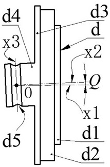
The invention relates to a self-powered monitoring rolling bearing, and belongs to the technical field of bearing monitoring and new energy. A partition plate on the inner wall of an outer ring divides the inner cavity of the outer ring into a left cavity and a right cavity, a circuit board and a sensor are installed on the partition plate, and the circuit board is arranged in the left cavity; anend cover is arranged at the end part of the left cavity and is used for pressing a positioning ring with upper and lower clamping grooves into the left cavity; an inner ring is mounted in the right cavity through a first rolling body; a half shaft is arranged at one end of a pendulum shaft, and a large plummer block and a small plummer block which are coaxial are arranged at the other end of thependulum shaft; a shaft inclination angle is formed between the inclined axis of the half shaft and the horizontal axis of the small plummer block; the large plummer block and the plummer block blockof the pendulum shaft are sleeved with an inner hole of the partition plate and an inner hole of the inner ring respectively, the large plummer block is connected with the inner ring, and the partition plate is arranged between a shaft shoulder and the inner ring; a pendulum ring is installed on the half shaft through a second rolling body, and when the half shaft rotates, the pendulum ring swingsaround the axial direction of the half shaft; and a piezoelectric vibrator is arranged on the outer edge of the pendulum ring, the piezoelectric vibrator and the sensor are connected with the circuitboard, and the free end of a piezoelectric vibrator is arranged in an upper clamping groove and a lower clamping groove of a positioning ring.

Description

technical field [0001] The invention belongs to the technical field of bearing monitoring and new energy, and in particular relates to a self-powered monitoring rolling bearing. Background technique [0002] Bearings are indispensable standard parts in the fields of machinery, vehicles, aerospace, ships and energy, and are also one of the most vulnerable parts in related transmission systems. 30% of the failures in rotating machinery are caused by bearing failure. Therefore, bearing condition monitoring and early fault diagnosis have attracted people's attention. On-line monitoring has gradually become the prerequisite for reliable operation of medium and large bearings in the fields of generators, ships, high-speed rail, and aircraft. The monitoring indicators involve temperature, vibration, speed, and noise. Early bearing monitoring systems were mainly plug-in. One of the disadvantages was that the distance between the sensor and the signal source was relatively long, and...

Claims


Application Information

Patent Timeline
Patent Type & Authority Applications(China)
IPC IPC(8): H02N2/18F03G3/06F03G7/08
CPCF03G3/06F03G7/08H02N2/186
Inventor 阚君武王凯吴亚奇张李翟仕杰曹红兵王淑云程光明
Owner ZHEJIANG NORMAL UNIVERSITY
Learn More