A steel block splitting and polishing equipment for high-end equipment manufacturing
A steel block and equipment technology, which is applied in the field of steel block segmentation and polishing equipment, can solve the problems of cumbersome steps, labor-intensive, dangerous, etc., and achieve the effect of simple and convenient operation and avoiding contact between grinding tools and cutting tools
- Summary
- Abstract
- Description
- Claims
- Application Information
AI Technical Summary
Problems solved by technology
Method used
Image
Examples
Embodiment 1
[0068] A steel block split polishing equipment for high-end equipment manufacturing, such as figure 1 and figure 2 As shown, it includes a bottom plate 1, a special-shaped track 2, a collection frame 3, a laser cutting gun 4, a feeding mechanism 5, and a grinding mechanism 6. A laser cutting gun 4 is connected between the left and right sides of the special-shaped track 2. A discharge mechanism 5 is provided on the special-shaped track 2. The discharge mechanism 5 is connected with the bottom plate 1 and the collection frame 3 respectively. 6.
[0069] Manually dividing and polishing steel blocks is dangerous, the steps are cumbersome and labor-intensive. This equipment can automatically divide and polish steel blocks, which is safe, easy to operate and can save manpower. The feeding mechanism 5 clamps the steel block, then starts the laser cutting gun 4, and makes the feeding mechanism 5 and the grinding mechanism 6 run, and the feeding mechanism 5 moves the steel block ba...
Embodiment 2
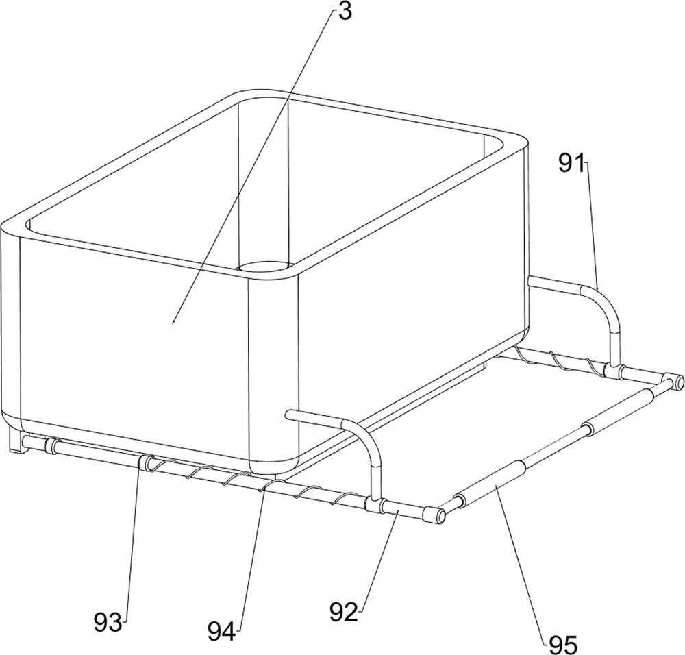
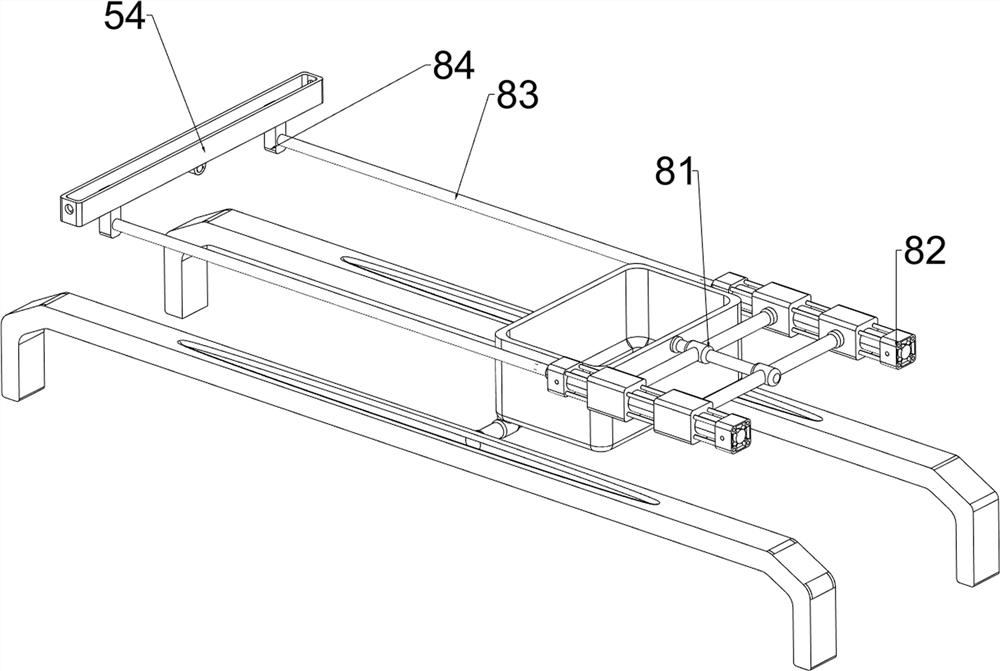
[0071] On the basis of Example 1, such as figure 2 and image 3 As shown, the discharge mechanism 5 includes a pillar 51, a first slide bar 52, a first spring 53, a straight slide rail 54, a second slide bar 55, a second spring 56, a circular post 57, and a first slide sleeve 58. , the third slide bar 59 and the third spring 510, the front middle part of the bottom plate 1 is provided with a pillar 51, the first slide bar 52 is connected between the top of the pillar 51 and the collection frame 3, and a sliding type is provided on the first slide bar 52 The word slide rail 54, the first slide bar 52 is wound with the first spring 53, the front side of the first spring 53 is connected with the word slide rail 54, the rear side of the first spring 53 is connected with the collection frame 3, the left and right sides of the word slide rail 54 Both sides are slidingly provided with a second slide bar 55, and the two second slide bars 55 are all wound with a second spring 56, the...
Embodiment 3
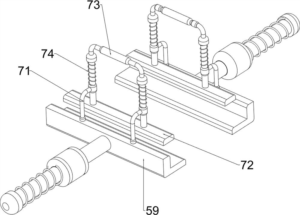
[0076] On the basis of Example 2, such as figure 1 , Figure 4 , Figure 5 , Figure 6 and Figure 7 As shown, a clamping mechanism 7 is also included, and the clamping mechanism 7 includes a second sliding sleeve 71, a splint 72, a first pull rod 73 and a fourth spring 74, and two second sliding rods are arranged on the inner side of the top of the third sliding rod 59. Cover 71, the first pull rod 73 is slidably connected between the inner side of the second sliding sleeve 71 on the front and rear sides, the first pull rod 73 on the left and right sides is all wound with a fourth spring 74 on both sides, the top of the fourth spring 74 is connected with The first pull rod 73 is connected, the bottom of the fourth spring 74 is connected with the second sliding sleeve 71 , and the bottoms of the first pull rod 73 on the left and right sides are provided with splints 72 , and the splints 72 cooperate with the third slide bar 59 .
[0077] When the third slide bar 59 moves t...
PUM
 Abstract
Description
Claims
Application Information
 - R&D
- Intellectual Property
- Life Sciences
- Materials
- Tech Scout
- Unparalleled Data Quality
- Higher Quality Content
- 60% Fewer Hallucinations
Browse by: Latest US Patents, China's latest patents, Technical Efficacy Thesaurus, Application Domain, Technology Topic, Popular Technical Reports.
© 2025 PatSnap. All rights reserved.Legal|Privacy policy|Modern Slavery Act Transparency Statement|Sitemap|About US| Contact US: help@patsnap.com


