Cutting device for hydraulic engineering pipeline paving

A technology for water conservancy engineering and cutting devices, which is used in grinding drive devices, metal processing equipment, grinding/polishing safety devices, etc., can solve the problem that the chips are easily splashed on the staff, endanger the health of the staff, and increase the cutting error. rate and other issues, to achieve the effect of protecting staff, reducing labor intensity, and reducing cutting error rate

Inactive Publication Date: 2021-02-09
仵蕾 +1
View PDF0 Cites 0 Cited by
  • Summary
  • Abstract
  • Description
  • Claims
  • Application Information

AI Technical Summary

Problems solved by technology

Water conservancy projects need to build different types of hydraulic structures such as dams, dikes, spillways, sluices, water inlets, canals, waterways, rafts, fishways, etc., to achieve their goals. During the construction of water conservancy projects, usually A large number of pipelines are used to transfer water resources, so the pipelines need to be spliced. During the splicing process, cutting devices are inevitably used to cut according to the length of the required pipelines. However, traditional cutting devices usually It is a hand-held device, which increases the labor intensity under long-term cutting, and the pipe needs to be fixed during the cutting process. The traditional fixing method usually uses manual fixing. Using this method to fix will easily lead to the displacement of the pipe, thereby increasing the The cutting error rate is increased, and at the same time, the chips generated during the cutting process are easy to splash on the staff, thus endangering the health of the staff

Method used


Image

  • Cutting device for hydraulic engineering pipeline paving
  • Cutting device for hydraulic engineering pipeline paving
  • Cutting device for hydraulic engineering pipeline paving

Examples


Embodiment Construction

[0021] The following will clearly and completely describe the technical solutions in the embodiments of the present invention with reference to the accompanying drawings in the embodiments of the present invention. Obviously, the described embodiments are only some, not all, embodiments of the present invention. Based on the embodiments of the present invention, all other embodiments obtained by persons of ordinary skill in the art without making creative efforts belong to the protection scope of the present invention.

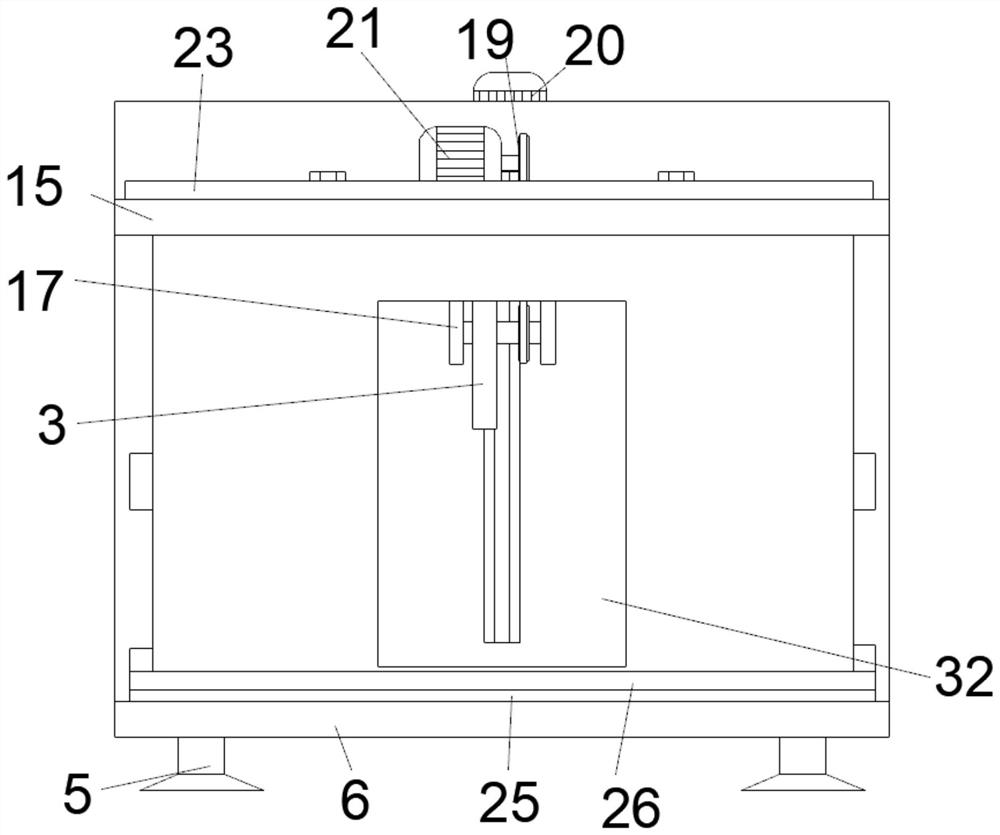
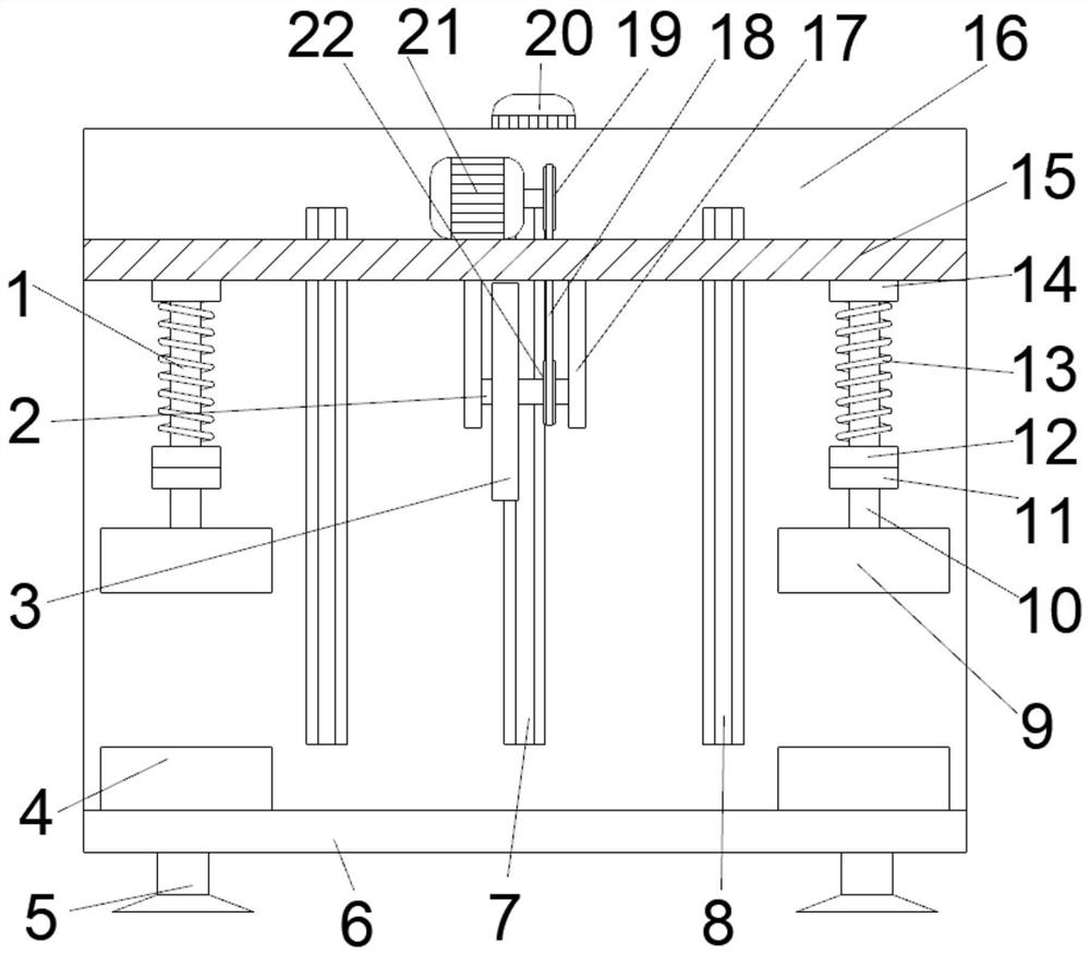
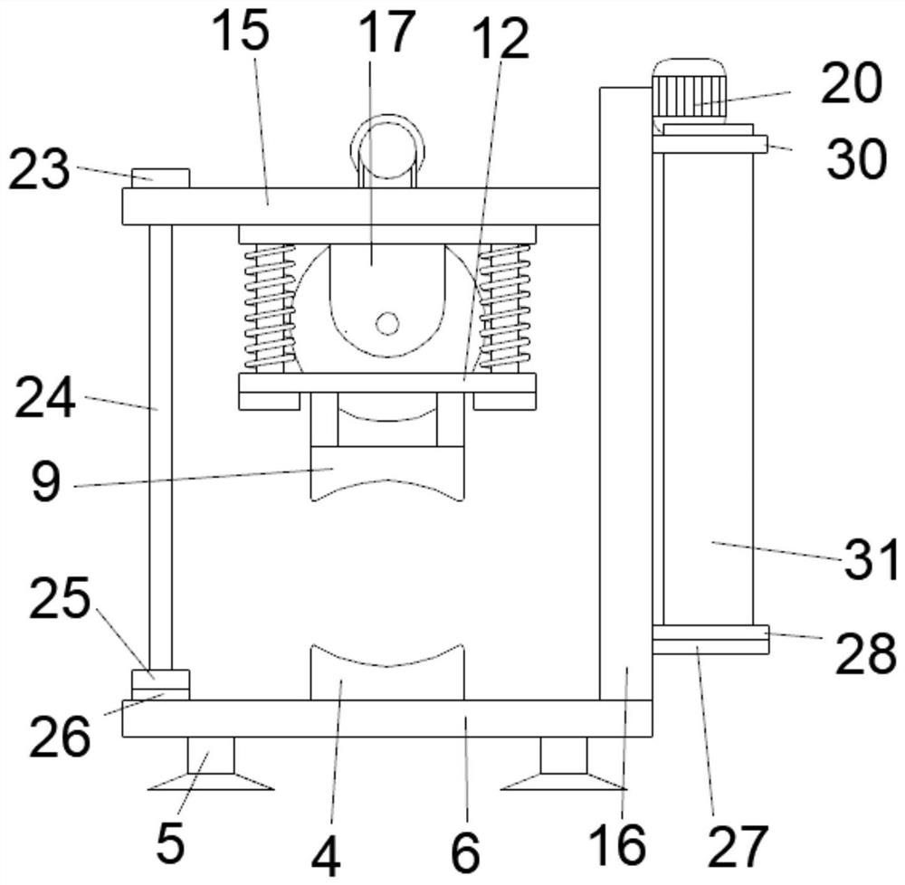
[0022] see Figure 1-5, the present invention provides a technical solution: a cutting device used for laying water conservancy engineering pipelines, including a limit column 1, a rotating shaft 2, a grinding wheel 3, a lower base 4, a support foot 5, a bottom plate 6, a screw rod 7, and a limit rod 8. Upper base 9, connecting rod 10, block 11, connecting plate 12, spring 13, first mounting plate 14, moving plate 15, side plate 16, fixed plate 17, chain 18, f...


PUM


Abstract

The invention discloses a cutting device for hydraulic engineering pipeline paving. The cutting device comprises a limiting column, a rotary shaft, a grinding wheel, a lower base, supporting legs, a bottom plate, a lead screw, a limiting rod, an upper base, a connecting rod, a baffle block, a connecting plate, a spring, a first mounting plate, a movable plate, side plates, a fixed plate, a chain,a first gear, a first motor, a second motor, a second gear, an upper baffle rod, a separating plate, a lower baffle rod, an anti-wear pad, a transverse plate, a U-shaped strip, a movable block, a second mounting plate, a U-shaped plate and a transparent plate. The separating plate is used for blocking cuttings, so that the cuttings are prevented from harming health of a worker; an upper base and alower base are used for fixing the cutting pipeline, so that the pipeline is prevented from moving in a cutting process, and thus, a cutting error rate is favorably reduced; and device changes a cutting way of conventional handheld cutting equipment; and the grinding wheel moves downwards for cutting the pipeline, so that labor intensity is reduced.

Description

technical field [0001] The invention relates to the technical field of cutting devices, in particular to a cutting device used for laying water conservancy engineering pipelines. Background technique [0002] Water conservancy projects are projects built to control and allocate natural surface water and groundwater to achieve the purpose of eliminating harm and rejuvenating profits. Also known as water engineering. Water is an indispensable precious resource for human production and life, but its natural state does not fully meet human needs. Only by building water conservancy projects can we control water flow, prevent floods, and regulate and distribute water to meet the needs of people's life and production for water resources. Water conservancy projects need to build different types of hydraulic structures such as dams, dikes, spillways, sluices, water inlets, canals, waterways, rafts, fishways, etc., to achieve their goals. During the construction of water conservancy...

Claims


Application Information

Patent Timeline
Patent Type & Authority Applications(China)
IPC IPC(8): B24B27/06B24B41/06B24B55/04B24B47/12
CPCB24B27/06B24B27/0691B24B41/067B24B47/12B24B55/04
Inventor 仵蕾田心勇
Owner 仵蕾
Why Eureka
Try Eureka