

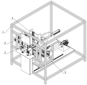
Inner and outer bag automatic thermal bonding device
A technology of thermal bonding and driving device, applied in the field of plastic woven bag manufacturing, can solve the problems of cumbersome manual fitting process, low degree of automation, low work efficiency, etc., and achieve the effects of stable operation, improved production efficiency and simple operation
- Summary
- Abstract
- Description
- Claims
- Application Information
AI Technical Summary
Problems solved by technology
Method used
Image

Examples
Embodiment Construction
[0042]In the description of the present application, it should be understood that the orientation or positional relationship indicated by the terms "center", "upper", "lower", "front", "rear", "left", "right" etc. are based on The orientations or positional relationships shown in the drawings are only for the convenience of describing the application and simplifying the description, and do not indicate or imply that the referred devices or components must have a specific orientation, be constructed and operated in a specific orientation, and therefore cannot be understood as Limitations on this Application. In this application, the opening mechanism is taken as an example for description. The location of the opening mechanism is the front, and the position opposite to the opening mechanism is the rear.
[0043] The principles and features of the present invention are described below in conjunction with the accompanying drawings, and the examples given are only used to explain ...
PUM
 Abstract
Description
Claims
Application Information