
Filtering and recycling system of suction pressure feed tank truck and suction pressure feed tank truck

A technology of suction, pressure delivery and recovery system, which is applied in the direction of conveyors, conveying bulk materials, separation methods, etc. It can solve the problems of easy blockage of recovery pipes, insufficient pressure bearing capacity, and insufficient connection, so as to improve safety and reliability. , reduce the risk of bursting, and facilitate daily maintenance

Pending Publication Date: 2021-02-09
SGIS SONGSHAN CO LTD
View PDF0 Cites 1 Cited by
  • Summary
  • Abstract
  • Description
  • Claims
  • Application Information

AI Technical Summary

Problems solved by technology

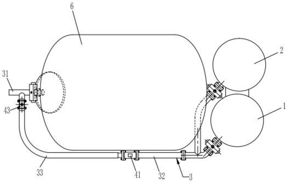
However, in the recovery pipeline of the existing filtration recovery system, the valve is usually located at one end close to the bag filter device. When the back suction method is used, the material is easy to enter the recovery pipeline, causing the recovery pipeline to be blocked.
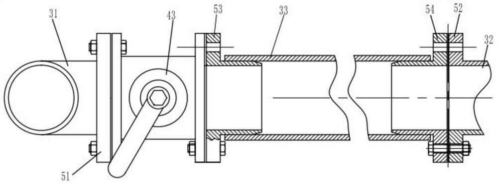
[0006] In addition, the hose quick connectors are often used to connect the various pipe sections in the recovery pipeline. The rubber hose quick connectors will wear out after a long time of use. If they are not replaced in time, the connection is not strong enough and the pressure bearing capacity is not enough Burst problem, there is a certain security risk
[0007] To sum up, in the existing filter recovery system for sucking and pressure-feeding tank trucks, the recovery pipeline has the defects of easy clogging when sucking back, easy wear and tear of the connecting structure, low service life, difficult maintenance and certain potential safety hazards

Method used


Image

  • Filtering and recycling system of suction pressure feed tank truck and suction pressure feed tank truck
  • Filtering and recycling system of suction pressure feed tank truck and suction pressure feed tank truck
  • Filtering and recycling system of suction pressure feed tank truck and suction pressure feed tank truck

Examples


Embodiment Construction

[0029]The present invention will be described in detail below with reference to the drawings and embodiments.

[0030]In the description of this application, it needs to be understood that orientation words such as “front, back, up, down, left, right”, “horizontal, vertical, horizontal” and “top, bottom” indicate the orientation or position The relationship is usually based on the orientation or position relationship shown in the drawings, which is only for the convenience of describing the application and simplifying the description. Unless otherwise stated, these orientation words do not indicate or imply that the device or element referred to must have The specific orientation or the construction and operation in a specific orientation cannot be understood as a limitation of the protection scope of this application.

[0031]For ease of description, spatially relative terms can be used here, such as "above", "above", "above the surface", "above", etc., to describe as shown in the figure...


PUM


Abstract

The invention relates to a filtering and recycling system of a suction pressure feed tank truck and the suction pressure feed tank truck. The filtering and recycling system comprises a recycling pipeline, a cloth bag filtering device and a cyclone separating device, and further comprises a flow control assembly, wherein the cloth bag filtering device and the cyclone separating device communicate with each other; one end of the recycling pipeline communicates with both the cloth bag filtering device and the cyclone separating device; the other end of the recycling pipeline is used for communicating with a storage tank; the flow control assembly comprises a flow detecting element, a control element and a valve; the valve is arranged on the recycling pipeline and positioned at the end close to the storage tank; the flow detecting element is arranged on the recycling pipeline and used for detecting the material flow in the recycling pipeline; the output end of the flow detecting element iselectrically connected with the input end of the control element; and the output end of the control element is electrically connected with the input end of the valve. The suction pressure feed tank truck comprises the above filtering and recycling system. Therefore, the recycling pipeline can be effectively prevented from being blocked during back suction, and then the normal use of the filteringand recycling system can be guaranteed.

Description

Technical field[0001]The invention relates to the technical field of suction and pressure feeding tank cars, and more specifically, it relates to a filter recovery system of a suction pressure feeding tank car and a suction pressure feeding tank car.Background technique[0002]The suction and pressure delivery tanker is a comprehensive principle of negative pressure pneumatic conveying and positive pressure pneumatic conveying of materials, and organically combines the two kinds of pneumatic conveying, using air as the carrier of material conveying, and realizing automatic suction of materials in a closed space. Special production equipment for materials, airtight transportation and automatic discharge. The suction and pressure delivery tanker is the transportation of dust materials such as ironmaking, steelmaking, sintering, coking, smelting desiliconization, desulfurization, dephosphorization, blast furnace, converter dust ash, etc. The entire suction, transportation and discharge p...

Claims


Application Information

Patent Timeline
Patent Type & Authority Applications(China)
IPC IPC(8): B65G53/36B65G53/04B01D50/00
CPCB01D50/00B65G53/04B65G53/36
Inventor 赖流永杨建波宋历武郑粤勇梁剑锋刘军李镜兴潘智明张满伦
Owner SGIS SONGSHAN CO LTD
Learn More