Debris flow drainage and guide structure
A technology of debris flow and diversion mechanism, applied in hydraulic engineering, artificial waterway, construction, etc., can solve the problems of insignificant energy dissipation and single function of debris flow, achieve simple structure, avoid destructive damage, reduce potential energy and speed Effect
- Summary
- Abstract
- Description
- Claims
- Application Information
AI Technical Summary
Problems solved by technology
Method used
Image
Examples
Embodiment 1
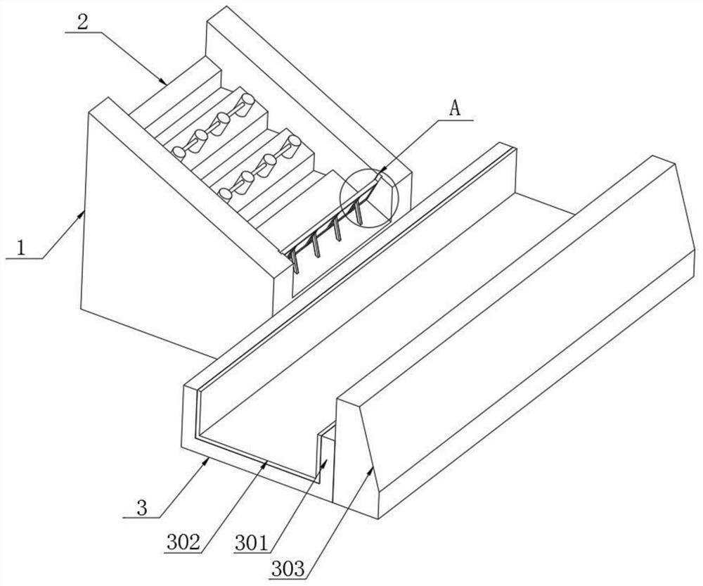
[0038] refer to Figure 1 to Figure 6 , a debris flow drainage structure of the present invention, comprising:
[0039] mountain 1;
[0040] The blocking mechanism 2 is arranged on the slope of the mountain and is used to block the downstream of the debris flow;
[0041]The flow diversion mechanism 3 is arranged at the bottom of the mountain and connected with the flow blocking mechanism, and is used for horizontally diverting the debris flow that slides down from the flow blocking mechanism; the flow blocking mechanism 2 includes at least two side walls 201 perpendicular to the mountain body, and the side walls 201 It is anchored on the mountain body 1; a number of concave energy dissipation grooves 202 are horizontally arranged between adjacent side walls; gravel 203 is laid on the bottom of the energy dissipation groove. The invention blocks the mud-rock flow through the flow blocking mechanism, reduces the potential energy of the mud-rock flow sliding down, and achieves ...
Embodiment 2
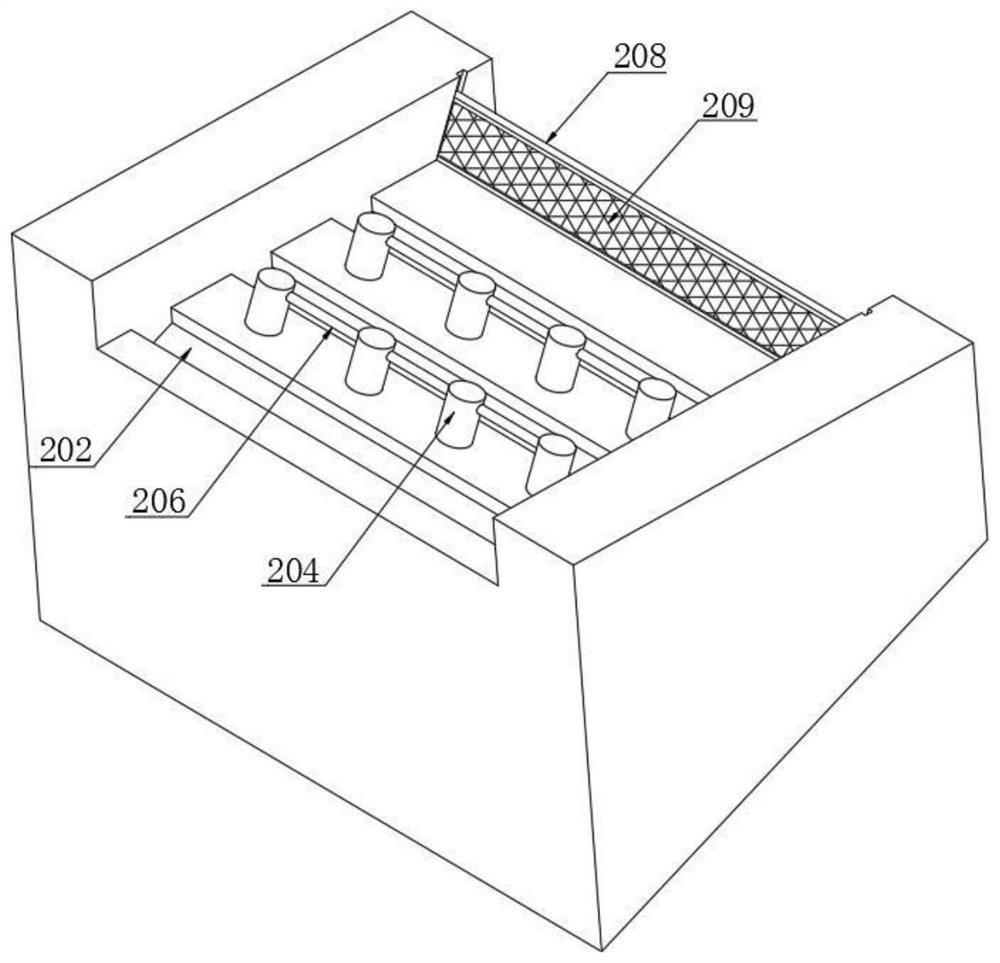
[0044] refer to image 3 with Figure 5 , on the basis of Embodiment 1, this embodiment is provided with several blocking piles 204 between adjacent energy dissipation grooves, and the ends of the blocking piles are provided with bases 205; the bases are buried in the mountain body, and the blocking piles protrude from the surface of the mountain body; adjacent blocking piles are connected by cross bars 206 . The blocking piles block the debris flow passing through and slow down the sliding speed of the debris flow; in addition, the crossbar connects the blocking piles in the same horizontal row, which enhances the overall strength of the blocking piles and improves the overall stability of the blocking piles and firmness, so as to ensure the retarding effect of the retarding pile on the debris flow.
[0045] refer to Figure 5 , the base 205 of this embodiment is tapered, and the base gradually increases in the direction away from the blocking pile; the base is provided wi...
Embodiment 3
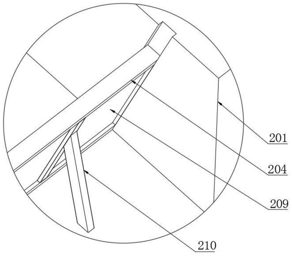
[0047] refer to figure 1 , figure 2 with image 3 , on the basis of Embodiment 1, this embodiment is provided with a blocking frame 208 inclined on the side of the flow blocking mechanism close to the flow guiding mechanism, and the blocking frame is clamped between two adjacent side walls; the blocking frame An intercepting net 209 is arranged on the 208 . The blocking frame plays a blocking role on the debris flow passing through, reduces the potential energy of the debris flow sliding down, and reduces the speed of the debris flow sliding; in summary, it can be seen that the present invention uses three measures to block the debris flow, which are respectively energy dissipation tank, Blocking piles and blocking frames, under the triple measures, can better block the debris flow, minimize the potential energy and speed of the debris flow, and prevent the debris flow from causing devastating damage to the building facilities or engineering facilities below the mountain. ...
PUM
 Abstract
Description
Claims
Application Information
 - R&D
- Intellectual Property
- Life Sciences
- Materials
- Tech Scout
- Unparalleled Data Quality
- Higher Quality Content
- 60% Fewer Hallucinations
Browse by: Latest US Patents, China's latest patents, Technical Efficacy Thesaurus, Application Domain, Technology Topic, Popular Technical Reports.
© 2025 PatSnap. All rights reserved.Legal|Privacy policy|Modern Slavery Act Transparency Statement|Sitemap|About US| Contact US: help@patsnap.com


