Bricklayer auxiliary device for building materials

An auxiliary device, bricklayer's technology, applied to clay preparation devices, construction, building construction, etc., to achieve the effect of easy operation and avoiding waste

Inactive Publication Date: 2021-02-09
那亚洲
View PDF8 Cites 0 Cited by
  • Summary
  • Abstract
  • Description
  • Claims
  • Application Information

AI Technical Summary

Problems solved by technology

[0003] The main technical problem to be solved by the present invention is to provide a bricklayer auxiliary device for building materials. This device is convenient for bricklayers to work indoors without continuous fi

Method used


Image

  • Bricklayer auxiliary device for building materials
  • Bricklayer auxiliary device for building materials
  • Bricklayer auxiliary device for building materials

Examples


specific Embodiment approach 1

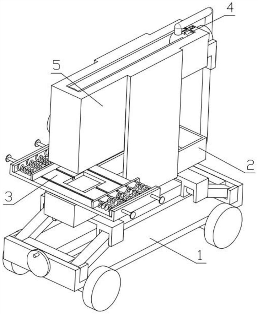
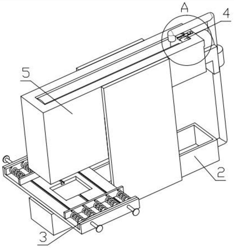
[0039] Combine below Figure 1-17Describe this embodiment, a bricklayer auxiliary device for building materials, including a lifting and moving mechanism 1, a waste water collection mechanism 2, a tile placement mechanism 3, a stirring and pushing mechanism 4, a top box body 5, and a feeding mechanism 6. The waste water collection mechanism 2 is fixedly installed on the mobile mechanism 1, the top box body 5 is fixedly installed on the waste water collection mechanism 2, the feeding mechanism 6 is fixedly installed on the top box body 5, and the tile placement mechanism 3 is fixedly installed on the waste water collection mechanism 2 Above, the stirring and pushing mechanism 4 is fixedly installed on the top box body 5 .

specific Embodiment approach 2

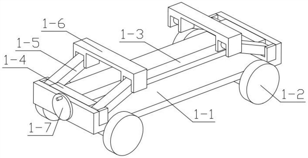
[0041] Combine below Figure 1-17 Describe this embodiment, this embodiment will further explain the first embodiment, the described lifting and moving mechanism 1 includes a vehicle chassis 1-1, a moving wheel 1-2, a two-way threaded rod 1-3, a push horizontal plate 1-4, Supporting hinge 1-5, U-shaped connecting plate 1-6, rotating disc 1-7, moving wheel 1-2 is installed in the groove provided on the vehicle chassis 1-1 in rotation, pushes the horizontal plate 1-4 to slide and install In the groove provided on the undercarriage 1-1, the two ends of the push cross plate 1-4 are respectively hinged with supporting hinges 1-5, and the other end of the supporting hinges 1-5 is hinged on the U-shaped connecting plate 1- 6, the two-way threaded rod 1-3 is rotatably installed in the groove provided on the undercarriage 1-1, and the rotating disk 1-7 is fixedly installed on one end of the two-way threaded rod 1-3, and the two-way threaded rod 1-3 is connected with the push Horizonta...

specific Embodiment approach 3

[0043] Combine below Figure 1-17 Describe this embodiment, this embodiment will further explain Embodiment 2. The waste water collection mechanism 2 includes a water tank 2-1, an upper water pipe 2-2, a water pump 2-3, a drain pipe 2-4, and a water tank 2-1 Fixedly installed on the U-shaped connecting plate 1-6, one end of the upper water pipe 2-2 is fixedly installed at the through hole provided on the water tank 2-1, and the other end of the upper water pipe 2-2 is fixedly installed on the water pump 2-3, The water pump 2-3 is fixedly installed with a drainage pipe 2-4, and the water pump 2-3 is fixedly installed on the top casing 5 .


PUM


Abstract

The invention relates to building material related devices, in particular to a bricklayer auxiliary device for building materials. The device comprises a lifting moving mechanism, a waste water collecting mechanism, a ceramic tile placing mechanism, a stirring and pushing mechanism, a top end box body and a feeding mechanism, wherein the waste water collecting mechanism is fixedly installed on thelifting moving mechanism, the top end box body is fixedly installed on the waste water collecting mechanism, the feeding mechanism is fixedly installed on the top end box body, the ceramic tile placing mechanism is fixedly installed on the waste water collecting mechanism, and the stirring and pushing mechanism is fixedly installed on the top end box body. The device facilitates a bricklayer to operate indoors, continuous filling is not needed, the device can ascend and descend, the problem that the bricklayer bends down to take materials during wall tiling is solved, the device has a stirring function, and manual stirring by the bricklayer is not needed.

Description

technical field [0001] The invention relates to a device related to building materials, more specifically a bricklayer auxiliary device for building materials. Background technique [0002] When a bricklayer is doing indoor decoration, he needs to install the mixed cement in a cement cylinder, which is easy to take and move, but it needs constant filling, and it takes a long time. The cement in the cement cylinder needs to be manually stirred by the bricklayer. When affixing wall tiles, it is necessary to bend down to fetch cement, which increases the workload of bricklayers virtually, and also lengthens the construction period of bricklayers. Contents of the invention [0003] The main technical problem to be solved by the present invention is to provide a bricklayer auxiliary device for building materials. This device is convenient for bricklayers to work indoors without continuous filling. The device can be lifted up and down, which solves the problem of bricklayers ben...

Claims


Application Information

Patent Timeline
IPC IPC(8): E04F21/18B28C9/04
CPCB28C9/04E04F21/18E04F21/1838
Inventor 那亚洲
Owner 那亚洲
Why Eureka
Try Eureka