
A kind of hydraulic casting wire salvage oil pipe internal blocking device and using method thereof

A steel wire and hydraulic technology, which is applied to the field of plugging devices in hydraulic wire salvage oil pipes, can solve the problems of plug resistance, oil pipe blockage, inconvenience in use, etc. Efficient effect

Active Publication Date: 2022-07-08
李达
View PDF10 Cites 0 Cited by
  • Summary
  • Abstract
  • Description
  • Claims
  • Application Information

AI Technical Summary

Problems solved by technology

When using the method of working under pressure, two problems must be solved first: one is the sealing of the annular space of the oil casing, and the other is the blockage problem in the oil pipe
[0005] 1. This kind of plug mainly relies on gravity to descend, and the descending speed is slow. The plugging process depends on the deformation of the expansion rubber tube caused by the downhole oil pressure for anchoring, and it cannot be plugged at the specified depth. For oil wells that require a deep sealing depth, not applicable;
[0006] 2. During the fishing process, due to the oil pressure on the upper part of the plug, resistance will be formed on the plug, resulting in slow upward movement;
[0007] 3. For this kind of plug, the upper part is mainly kept in place by sliding slips, and the effect of sliding slips attached to the inner wall of the oil pipe is not good, and it is easy to move upwards, resulting in the failure of the expansion rubber tube to be squeezed and deformed, which affects the sealing effect;
[0008] 4. Since the plug relies on gravity to descend, it has high requirements for the inner wall of the oil well. It is mostly used in water injection wells, and the oil well needs to be cleaned in advance, which is inconvenient to use.

Method used


Image

  • A kind of hydraulic casting wire salvage oil pipe internal blocking device and using method thereof
  • A kind of hydraulic casting wire salvage oil pipe internal blocking device and using method thereof
  • A kind of hydraulic casting wire salvage oil pipe internal blocking device and using method thereof

Examples


Embodiment Construction

[0036] The specific content of the present invention will be described in detail below with reference to the accompanying drawings and specific embodiments.

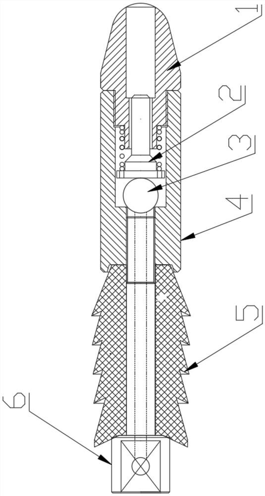
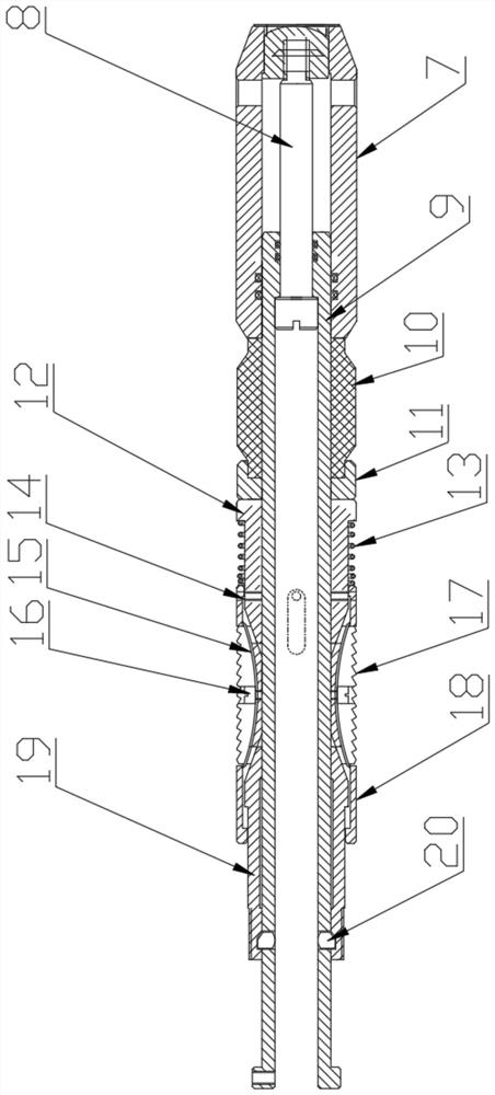
[0037] like figure 1 As shown in the figure, a hydraulic casting wire salvage oil pipe internal blocking device includes a guide mechanism, a seat sealing mechanism, and a salvage mechanism.

[0038] like figure 2 As shown, the guide mechanism includes a guide head 1, a valve core 2, a valve ball 3, a valve body 4, a glue tower 5, and a glue tower shaft 6; A valve body 4 is detachably connected to the rear of the head 1; the valve body 4 is cylindrical, the center is through, a cavity is formed between the valve body 4 and the guide head 1, and the valve ball 3 and the valve core 2 are installed in the cavity. , the valve core 2 is a rotary part with a T-shaped cross section, the valve core 3 bears against the rear through hole of the valve body 4, the upper big end of the valve core 2 is close to the valve core 3, and ...


PUM


Abstract

The invention discloses an inner plugging device for a hydraulic-casting steel wire salvage oil pipe and a method for using the same. The plugging device comprises a guide mechanism, a seating mechanism and a salvage mechanism, and the guide mechanism includes a guide head, a valve core, a valve ball and a valve body. , rubber tower, rubber tower shaft; the guide head is conical, the rubber tower is cylindrical rubber, and the outer side is provided with a plurality of unidirectional zigzag rubber rings. The seat sealing mechanism includes an inclined pusher, a sealing shaft, a central shaft, a rubber cylinder, a gland, a lower cone sleeve, a limit spring leaf spring, slips, a slip sleeve, an upper cone sleeve, and a stopper; the inclined pusher , Rubber barrel, gland, lower cone sleeve, slips, slip sheath, upper cone sleeve are sleeved on the central shaft in sequence from front to back. The salvage mechanism includes a fixed sleeve, a pin shaft, a shear nail, a pawl, a torsion spring, a limit shaft, and a salvage joint. The middle part of the limit shaft is provided with a pawl through the pin shaft, and the front part of the salvage joint is connected to the pin shaft. . The delivery efficiency of the present invention is higher, and the sealing stability is strong, and the realization is easy.

Description

technical field [0001] The invention belongs to the field of blowout prevention and blocking in high-pressure oil pipes, and in particular relates to an internal blocking device for a hydraulic-casting wire fishing oil pipe and a method for using the same. Background technique [0002] When oil wells or water injection wells are used for downhole operations, if there is pressure downhole, it is usually necessary to perform well killing or blowout and pressure reduction treatment first. For well killing operations, during the well killing process, the well killing fluid will precipitate and pollute the bottom of the well, and some of it will even penetrate into the formation along pores or cracks, block the gas flow channel, pollute the production layer near the bottom of the well, and affect the permeability of the formation. , resulting in reduced production and reduced oil recovery. In addition, for low-pressure oil and gas wells, it is difficult to discharge the killing ...

Claims


Application Information

Patent Timeline
Patent Type & Authority Patents(China)
IPC IPC(8): E21B33/126E21B33/1295E21B33/06E21B31/12E21B34/00
CPCE21B33/1265E21B33/1295E21B33/06E21B31/12E21B34/00
Inventor 李达
Owner 李达
Learn More