Novel direct type backlight module and LED light-emitting device thereof

A backlight module and light-emitting device technology, which is applied in the direction of optical components, light guides, optics, etc., can solve the problems of high process cost, non-vertical, and inability to control in different areas, and achieve low process cost, thinness, and picture effect Good results

Pending Publication Date: 2021-02-09
吴冬梅
View PDF0 Cites 0 Cited by
  • Summary
  • Abstract
  • Description
  • Claims
  • Application Information

AI Technical Summary

Problems solved by technology

The disadvantages are: 1. There are few LED particles, limited by the number of LED particles and brightness, the larger the area of ​​the display, the more limited the use of light source brightness, and the picture effect is not very good; 2. Cannot be controlled by area
The disadvantages are: 1. The thickness of the direct-type backlight module is large, which affects the appearance and seriously affects the marketing; 2. There are many LED particles and the repair rate is high
The technical key of this new direct type backlight module lies in how to change the running direction of the light so that the light is evenly emitted from the direction perpendicular to the upper surface of the light guide plate. If the running direction of the light is not changed, the light emitted from the light guide plate is not vertical and uneven
In the prior art, there are some methods to change the running direction of light, for example: setting an inverted cone-shaped or inverted triangle cavity in the light guide plate, or setting a cone-shaped or triangular barrier wall in the adjacent area of ​​​​the LED particles , but the light emitted from the light guide plate is not uniform and not vertical. At the same time, these special-shaped bodies have poor controllability to the light, and the light guide plate emitted from the top of the cone-shaped and inverted triangular cavity will form light spots, and the picture effect is not good. Great, in addition, the structure of these backlight modules is relatively complicated, and the process cost is high

Method used


Image

  • Novel direct type backlight module and LED light-emitting device thereof
  • Novel direct type backlight module and LED light-emitting device thereof
  • Novel direct type backlight module and LED light-emitting device thereof

Examples


Embodiment 1

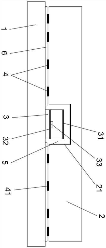
[0048] A novel direct-type backlight module LED light-emitting device, such as figure 1 As shown, it includes: a substrate 1, a light guide plate 2, LED particles 3, and a dot layer 4, the light guide plate 2 is located above the dot layer 4, the substrate 1 is located below the dot layer 4, and the LED particles 3 are fixed on the dot layer of the substrate 1. The upper surface, and the LED particles 3 are arranged in the LED installation chamber 21 of the light guide plate 2, the lower surface of the LED installation chamber 21 is flush with the lower surface of the light guide plate 2, and the upper and lower parts of the LED particles 3 are provided with a small reflective layer 31. Light is emitted from the surroundings of the LED particles 3 .

[0049] There is a gap 5 between the LED particle 3 and the upper surface and surroundings of the LED installation chamber 21, and the upper surface of the LED installation chamber 21 is provided with a reflective layer, which is ...

Embodiment 2

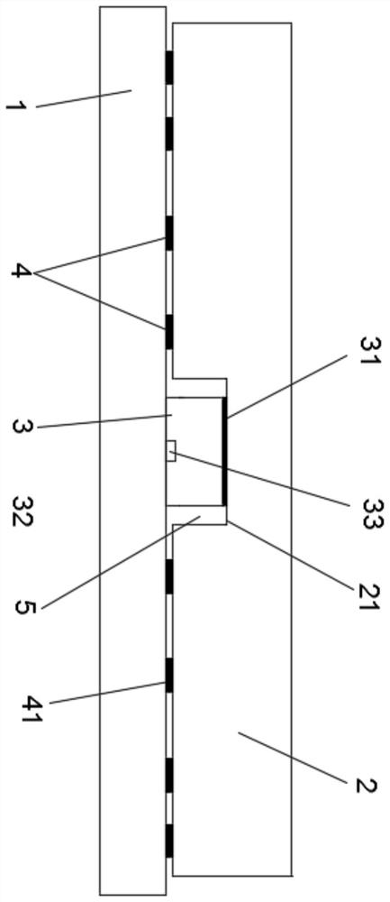
[0053] A novel direct-type backlight module LED light-emitting device, such as figure 2 As shown, it includes: a substrate 1, a light guide plate 2, LED particles 3, and a dot layer 4, the light guide plate 2 is located above the dot layer 4, the substrate 1 is located below the dot layer 4, and the LED particles 3 are fixed on the dot layer of the substrate 1. The upper surface, and the LED particles 3 are arranged in the LED installation chamber 21 of the light guide plate 2, the lower surface of the LED installation chamber 21 is flush with the lower surface of the light guide plate 2, and the upper and lower parts of the LED particles 3 are provided with a small reflective layer 31. Light is emitted from the surroundings of the LED particles 3 .

[0054] There is no gap between the LED particle 3 and the upper surface of the LED installation chamber 21 , but there is a gap 5 around the LED particle 3 and the LED installation chamber 21 , and the gap 5 is filled with a tra...

Embodiment 3

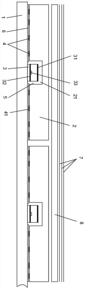
[0058] A new type of direct-lit backlight module, such as image 3 As shown, it includes: a substrate 1, a light guide plate 2, LED particles 3, and a dot layer 4, the light guide plate 2 is located above the dot layer 4, the substrate 1 is located below the dot layer 4, and the LED particles 3 are fixed on the dot layer of the substrate 1. The upper surface, and the LED particles 3 are arranged in the LED installation chamber 21 of the light guide plate 2, the lower surface of the LED installation chamber 21 is flush with the lower surface of the light guide plate 2, and the upper and lower parts of the LED particles 3 are provided with a small reflective layer 31 , light is emitted from the surroundings of the LED particles 3 , and other optical films 7 are also included, and the other optical films 7 are located above the light guide plate 2 .

[0059] There are gaps 5 between the LED particles 3 and the upper surface and surroundings of the LED installation chamber 21 , an...


PUM

PropertyMeasurementUnit
Thicknessaaaaaaaaaa
Thicknessaaaaaaaaaa

Abstract

According to the novel direct type backlight module and the LED light-emitting device thereof, the effect of the light guide plate is truly and perfectly applied to the direct type backlight module, and the direct type backlight module is thin, good in picture display effect, simple in structure, low in process cost, capable of being controlled in a regional mode and low in repair rate; the LED light-emitting device comprises a substrate 1, a light guide plate 2, LED particles 3 and a dot layer 4; the light guide plate 2 is located above the dot layer 4, the substrate 1 is located below the dot layer 4, the LED particles 3 are fixed to the upper surface of the substrate 1, the LED particles 3 are arranged in an LED installation cavity 21 of the light guide plate 2, and the lower surface ofthe LED installation cavity 21 is flush with the lower surface of the light guide plate 2. Small reflecting layers 31 are arranged on the upper portions and the lower portions of the LED particles 3,and light is emitted from the peripheries of the LED particles 3.

Description

technical field [0001] The present invention relates to the technical field of display devices, and more specifically, to a novel direct-lit backlight module and an LED light-emitting device thereof. Background technique [0002] The backlight module of a TV or computer display device is divided into a side-type backlight module and a direct-type backlight module, wherein: the LED particles of the side-type backlight module are placed on the side of the light guide plate, and the light passes through the side of the light guide plate. Refraction, and then diffuse reflection through the dots at the bottom of the light guide plate, so that the light is evenly emitted from the direction perpendicular to the upper surface of the light guide plate. Its advantages are: 1. The thickness of the side-type backlight module is small; 2. There are few LED particles, and the repair rate is low. The disadvantages are: 1. There are few LED particles, limited by the number of LED particles...

Claims


Application Information

Patent Timeline
IPC IPC(8): G02B6/00
CPCG02B6/0051G02B6/0055G02B6/0073G02B6/009
Inventor 李秀富
Owner 吴冬梅
Why Eureka
Try Eureka