Transformer oil conservator dehumidification device based on image humidity recognition and dehumidification method thereof

A technology of transformer oil and humidity, applied in transformer/inductor cooling, humidity control, instruments, etc., can solve the problems of reducing the deterioration speed of insulating oil, affecting the performance of insulating oil, and reducing dehumidification effect, so as to reduce manual participation and reduce Labor intensity and the effect of reducing the rate of deterioration

Pending Publication Date: 2021-02-09
JIYUAN POWER SUPPLY COMPANY OF STATE GRID HENAN ELECTRIC POWER
View PDF0 Cites 1 Cited by
  • Summary
  • Abstract
  • Description
  • Claims
  • Application Information

AI Technical Summary

Problems solved by technology

[0002] With the development of society, the trend of automation equipment to replace manual tasks is becoming more and more obvious, and the precision of automation equipment is also increasing, and the requirements for de-manualization in various high-risk jobs are also gradually increasing; the air on the upper part of the general oil conservator It is connected to the outside by a ventilation pipe. In order to prevent the moisture in the air from entering the oil conservator through the ventilation pipe and reducing the insulation performance of the insulating oil, a desiccant is generally placed in the ventilation pipe to dehumidify. However, as the desiccant absorbs more moisture, Its dehumidification effect is also declining, and even after absorbing water, it will release water into the oil conservator to affect the performance of insulating oil. Usually, the above problems can be solved by replacing the desiccant, but due to the dryness in the ventilation duct of the oil conservator Therefore, the present invention proposes an automatic dehumidification device for oil pillow desiccant for transformers, which can greatly reduce the manual participation in the daily maintenance of transformers, and achieve the effect of replacing the process of manual replacement of desiccant. At the same time, the deterioration rate of insulating oil is greatly reduced

Method used


Image

  • Transformer oil conservator dehumidification device based on image humidity recognition and dehumidification method thereof
  • Transformer oil conservator dehumidification device based on image humidity recognition and dehumidification method thereof

Examples


Embodiment 1

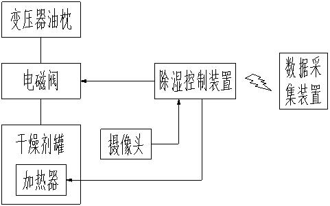
[0025] Such as Figure 1-2 As shown, the transformer oil conservator dehumidification device based on image humidity recognition includes a solenoid valve, a desiccant tank, a heater, a camera, a dehumidification control device, and a data acquisition device. The solenoid valve is connected between the desiccant tank and the transformer oil Between the pipelines of the pillow, the heater is set in the desiccant tank for heating the wet desiccant; the camera is set outside the desiccant tank, and the heater and the solenoid valve control The terminals are respectively connected to the output control ports of the dehumidification control device; the output terminals of the camera are connected to the input ports of the dehumidification control device; the data information is transmitted wirelessly between the dehumidification control device and the data acquisition device ;

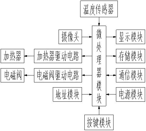
[0026] The dehumidification control device includes a heater driving circuit, a solenoid valve driving ...

Embodiment 2

[0035] Such as Figure 1-2 As shown, the transformer oil conservator dehumidification device based on image humidity recognition includes a solenoid valve, a desiccant tank, a heater, a camera, a dehumidification control device, and a data acquisition device. The solenoid valve is connected between the desiccant tank and the transformer oil Between the pipelines of the pillow, the heater is set in the desiccant tank for heating the wet desiccant; the camera is set outside the desiccant tank, and the heater and the solenoid valve control The terminals are respectively connected to the output control ports of the dehumidification control device; the output terminals of the camera are connected to the input ports of the dehumidification control device; the data information is transmitted wirelessly between the dehumidification control device and the data acquisition device ;

[0036] The dehumidification control device includes a heater driving circuit, a solenoid valve driving ...


PUM


Abstract

The invention belongs to the technical field of dehumidification devices, and particularly relates to a transformer oil conservator dehumidification device based on image humidity recognition and a dehumidification method thereof. The dehumidification device comprises an electromagnetic valve, a drying agent tank, a heater, a camera, a dehumidification control device and a data acquisition device,wherein the electromagnetic valve is connected between the drying agent tank and a pipeline of the transformer oil conservator, the heater is arranged in the drying agent tank, and the camera is arranged outside the drying agent tank. The heater and the control end of the electromagnetic valve are respectively connected with an output control port of the dehumidification control device; the output end of the camera is connected with the input port of the dehumidification control device; the dehumidification control device comprises a heater driving circuit, an electromagnetic valve driving circuit, an address module, a microprocessor module, a display module, a key module, a storage module, a communication module, a power supply module and a temperature sensor. The effect of replacing a drying agent manually is achieved, the degradation speed of the insulating oil is reduced, the labor intensity is reduced, and the working efficiency is improved.

Description

technical field [0001] The invention belongs to the technical field of dehumidification devices, and in particular relates to a transformer oil conservator dehumidification device based on image humidity recognition and a dehumidification method thereof. Background technique [0002] With the development of society, the trend of automation equipment to replace manual tasks is becoming more and more obvious, and the precision of automation equipment is also increasing, and the requirements for de-manualization in various high-risk jobs are also gradually increasing; the air on the upper part of the general oil conservator It is connected to the outside by a ventilation pipe. In order to prevent the moisture in the air from entering the oil conservator through the ventilation pipe and reducing the insulation performance of the insulating oil, a desiccant is generally placed in the ventilation pipe to dehumidify. However, as the desiccant absorbs more moisture, Its dehumidifica...

Claims


Application Information

Patent Timeline
Patent Type & Authority Applications(China)
IPC IPC(8): G05D22/02G01N21/81H01F27/14
CPCG01N21/81G05D22/02H01F27/14
Inventor 霍明霞苗堃齐文炎李峙韩光李杰张永乐赵双兵孟书海刘洋翟波
Owner JIYUAN POWER SUPPLY COMPANY OF STATE GRID HENAN ELECTRIC POWER
Why Eureka
Try Eureka