Permeation grouting process simulation method and system based on DEM-CFD coupling

A DEM-CFD, process simulation technology, applied in the field of computational fluid dynamics simulation, can solve problems such as difficulty in considering the interaction between rock and soil and grout, and difficulty in simulating the process of infiltration and grouting

Active Publication Date: 2021-02-09
SHANDONG UNIV
View PDF6 Cites 5 Cited by
  • Summary
  • Abstract
  • Description
  • Claims
  • Application Information

AI Technical Summary

Problems solved by technology

[0005] As far as the inventor knows, a large number of scholars at home and abroad have simulated the seepage grouting process through theoretical calculations, finite element and discrete element numerical simulation methods, but considering that it is difficult to simultaneously simulate the two processes of rock and soil strength improvement and grout seepage with a single calculation method , especially it is difficult to consider the interaction between rock-soil mass and grout, and it is difficult to realize the simulation of seepage grouting process

Method used


Image

  • Permeation grouting process simulation method and system based on DEM-CFD coupling
  • Permeation grouting process simulation method and system based on DEM-CFD coupling
  • Permeation grouting process simulation method and system based on DEM-CFD coupling

Examples


Embodiment 1

[0039] This embodiment provides a DEM-CFD coupling-based infiltration grouting process simulation method. This embodiment takes the infiltration grouting process in water-rich and broken strata as an example. It can be understood that this embodiment can also be applied to loose sandy soil Layers or cracked rock formations and other formations where the permeable grouting method is applicable;

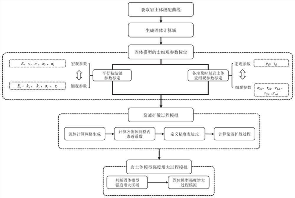
[0040] Such as figure 1 As shown, a method for simulating the infiltration grouting process in water-rich fractured formations based on DEM-CFD coupling provided in this embodiment includes the following steps:

[0041] Step 1: Obtain the particle grading curve of rock and soil mass.

[0042] The rock and soil samples were obtained from the area that needs to be infiltrated and grouted, and the indoor sieving experiment was carried out to obtain the particle gradation curve of the rock and soil samples.

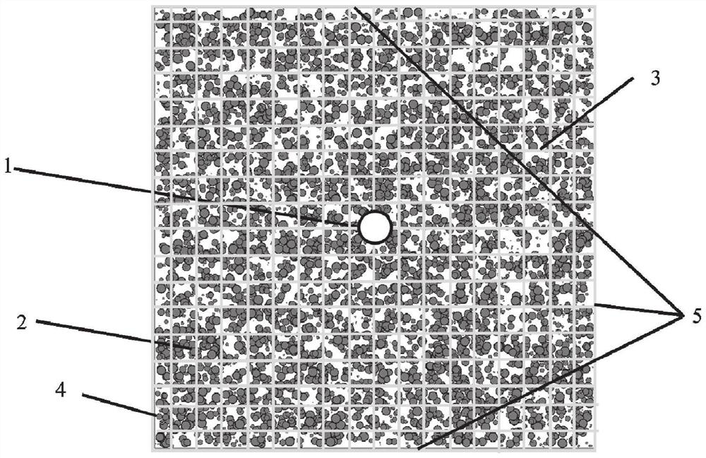
[0043] Step 2: Generate a solid calculation model according to the particle gra...

Embodiment 2

[0071] This embodiment provides a DEM-CFD coupling-based infiltration grouting process simulation system, including:

[0072] A rock and soil mass parameter acquisition module configured to acquire a rock and soil mass particle grading curve;

[0073] A calculation model generation module configured to generate a rock and soil calculation model according to the particle gradation curve;

[0074] The model initialization module is configured to obtain the initial parameters of the parallel bonding bond, and initialize the strength of the rock and soil mass calculation model;

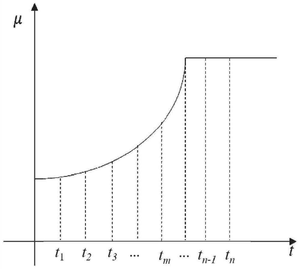
[0075] The infiltration grouting process simulation module is configured to divide the information grid of the rock and soil calculation model to generate a fluid calculation grid; according to the permeability coefficient of the fluid calculation grid and the time-space characteristics of fluid viscosity, the simulation of the grout diffusion process is performed; according to The grout diffusion proces...


PUM


Abstract

The invention provides a permeation grouting process simulation method and system based on DEM-CFD coupling. The method comprises the steps: obtaining a rock-soil body grain composition curve; generating a rock-soil body calculation model according to the grain composition curve; obtaining parallel bond initial parameters, and initializing the strength of the rock-soil body calculation model; dividing the rock-soil body calculation model information into grids to generate fluid calculation grids; and simulating the slurry diffusion process according to the permeability coefficient of the fluidcalculation grid and the space-time characteristic of the fluid viscosity. According to the invention, the interaction between the rock-soil body and the slurry can be considered, and the real simulation of the permeation grouting process is achieved.

Description

technical field [0001] The invention relates to the technical field of computational fluid dynamics (CFD) simulation, in particular to a method and system for simulating a seepage grouting process based on DEM-CFD coupling. [0002] technical background [0003] Faults, karst and other adverse geology are often encountered in the construction of tunnel projects, resulting in frequent engineering disasters and posing serious challenges to project safety construction, people's life and property protection, and ecological environment protection. Grouting reinforcement technology has been widely used in the tunnel excavation construction process. Through hydraulic, pneumatic or electrochemical methods, some grout that can be well consolidated with rock and soil is injected into the pores and cracks of rock and soil. In order to make rock and soil become a new structure with high strength, good impermeability and high stability, so as to achieve the purpose of improving the physic...

Claims


Application Information

Patent Timeline
Patent Type & Authority Applications(China)
IPC IPC(8): G06F30/28
CPCG06F30/28Y02A10/40
Inventor 周宗青白松松林春金高成路屠文锋魏车车王超王美霞陈雨雪
Owner SHANDONG UNIV
Why Eureka
Try Eureka