
Luneberg lens reflector and passive radar reflection ball comprising same

A Lumberg lens, passive radar technology, applied in instruments, radio wave measurement systems, measurement devices, etc., can solve the problems of reflection area influence, reflection area instability due to environmental influence, and radar false target construction reflection area, etc. Solve the effect of inconvenient processing

Active Publication Date: 2021-02-09
XIAMEN HUAXIA UNIV
View PDF16 Cites 2 Cited by
  • Summary
  • Abstract
  • Description
  • Claims
  • Application Information

AI Technical Summary

Problems solved by technology

[0007] The purpose of the present invention is to provide a Lunberg lens reflector and a passive radar containing it in order to overcome the problems of radar false target construction, small reflection area, and unstable reflection area affected by the environment in the existing passive radar simulation. reflective ball
[0008] The present invention solves the problem of using Lumber lens technology to realize the large-area radar reflection area, and the problem of the influence of the external conditions on the water surface on the reflection area

Method used


Image

  • Luneberg lens reflector and passive radar reflection ball comprising same
  • Luneberg lens reflector and passive radar reflection ball comprising same
  • Luneberg lens reflector and passive radar reflection ball comprising same

Examples


Embodiment 1

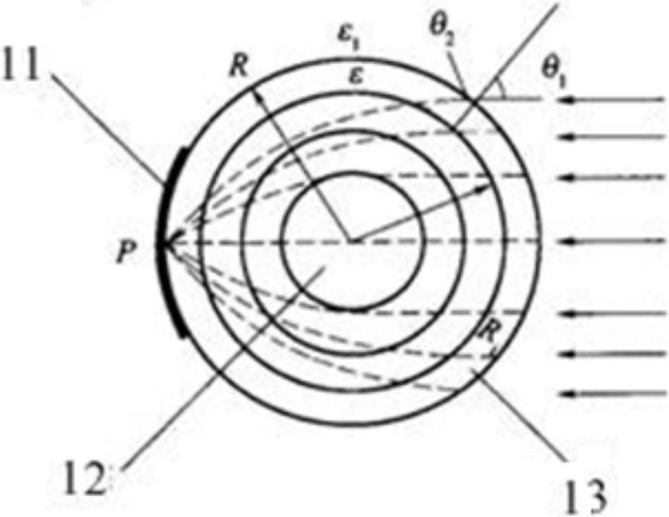
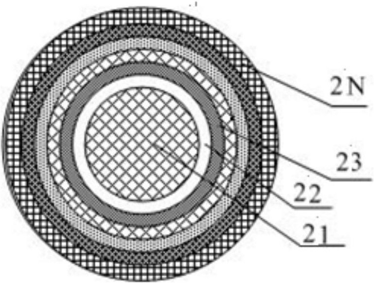
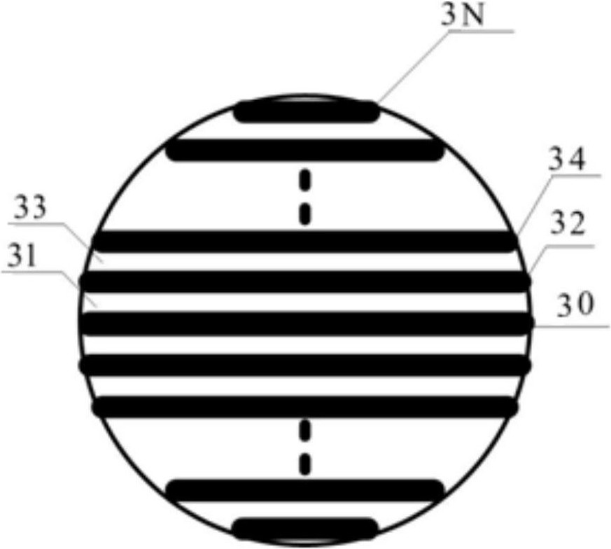
[0043] refer to figure 1 , figure 2 and image 3 , the Lunberg lens reflector includes a spherical core, the first dielectric spherical layer surrounds the outside of the spherical core, the second dielectric spherical layer surrounds the outside of the first dielectric spherical layer, and so on, the dielectric spherical layer N is surrounded by the outermost layer. The dielectric constants of different dielectric spherical layers are different, and gradually decrease from the center of the sphere to the outside. It is preferable that the dielectric constant of the outermost layer is the same as that of air. Different dielectric layers have different thicknesses.

[0044] The bottom of the Lunberg lens reflector is provided with a circular arc surface reflection area for converging electromagnetic waves for reflection, preferably the arc surface is a metal reflection area.

[0045] figure 2 is a top view schematic diagram of the medium layer structure of the maximum di...

Embodiment 2

[0047] A molding method of a Lunberg lens reflector, comprising the following steps:

[0048] s01, perform parameter design according to the reflective area of ​​the Lunberg lens reflector body, the parameter design is to first determine the radius of the sphere and the thickness of the dielectric sphere layer, the dielectric sphere layer contains a plurality of dielectric layers with different dielectric constants, and then determine the medium The number of layers and the corresponding thickness of the dielectric layer gradually expand from the dielectric layer close to the center of the sphere to the outermost dielectric layer, thereby dividing the Lunberg lens reflector body into multiple circles;

[0049] s02, the designed circle is formed by 3D printing, and the next layer is printed after one layer is printed;

[0050] s03, use the medium to print the metal reflective surface in the arc area;

[0051] s04, splicing the dielectric sphere and the metal reflective surface...

Embodiment 3

[0055] refer to Figure 4 , a passive radar reflector, comprising a shell 1, a Lunberg lens reflector 2, a handle 3, and a chassis 4, wherein the shell 1 is hollow, the Lunberg lens reflector 2 is arranged inside the shell 1, and the chassis 4 is fixed Connected to the bottom of the housing 1, a handle 3 is arranged symmetrically in the middle of the outer wall of the housing 1, for connecting the radar reflecting spheres in series.

[0056] Preferably, the housing 1 is a rigid spherical shape, and the mass of the Lunberg lens reflector 2 is greater than that of the housing 1 , so that the chassis 4 , the housing 1 and the Lunberg lens reflector 2 form a tumbler structure.

[0057] In other embodiments, the handle 3 can also be arranged on the chassis 4 .


PUM


Abstract

The invention relates to a Luneberg lens reflector and a passive radar reflection ball comprising the Luneberg lens reflector. The Luneberg lens reflector is formed by printing through the 3D technology, the passive radar reflection ball comprises a wave lens reflector ball, the Luneberg lens reflector further comprises a chassis and a hollow shell, the chassis is fixedly connected to the bottom of the shell, and a handle is arranged on the outer wall of the shell; the luneberg lens reflector is arranged in the shell, the dielectric constant of the dielectric sphere layer is gradually reducedfrom the sphere center to the outside, and a reflection area is arranged at the bottom of the luneberg lens reflector. The Luneberg lens reflector has a better reflection effect, the passive radar reflection balls are high in anti-interference capability, a plurality of passive radar reflection balls are connected in series to form a passive cascaded radar reflection ball false target, and the problems that the reflection area is limited and reflection signals are interfered by the environment in passive radar signal simulation are solved.

Description

technical field [0001] The invention relates to the technical field of passive radar false target simulation, in particular to a Lunberg lens reflector and a passive radar reflector containing the same, which are used for the simulation of radar false targets on water. Background technique [0002] At present, it is more practical to simulate the false target of the passive radar on the water by using the inflatable corner reflector to simulate. Although this reflector is easy to use, it can be directly projected and automatically inflated to open, but the practical effect is due to the use of the inflatable type to float on the water surface. The change of sea waves will have a great impact on its radar reflection area, that is, the radar reflection area will vary greatly with different sea conditions or water conditions and meteorological conditions, which limits its use to some extent. In particular, the reflector cannot be dragged with a certain speed, because this will ...

Claims


Application Information

Patent Timeline
Patent Type & Authority Applications(China)
IPC IPC(8): H01Q15/16G01S7/40
CPCH01Q15/16G01S7/4052G01S7/4082
Inventor 张树森陈明明周海波
Owner XIAMEN HUAXIA UNIV
Learn More