
Transformer substation monitoring device

A technology for monitoring devices and substations, applied to switchgear, electrical components, etc., can solve the problems of low accuracy and cumbersome manual monitoring

Active Publication Date: 2021-02-09
LIANGSHAN POWER SUPPLY CO OF STATE GRID SHANDONG ELECTRIC POWER CO +2
View PDF4 Cites 0 Cited by
  • Summary
  • Abstract
  • Description
  • Claims
  • Application Information

AI Technical Summary

Problems solved by technology

[0009] However, in the prior art, no automatic monitoring device is disclosed, and the monitoring of working equipment requires manual monitoring, which is not only cumbersome, but also has low accuracy of manual monitoring

Method used


Image

  • Transformer substation monitoring device
  • Transformer substation monitoring device
  • Transformer substation monitoring device

Examples


Embodiment 1

[0044] Embodiment 1 Substation monitoring device

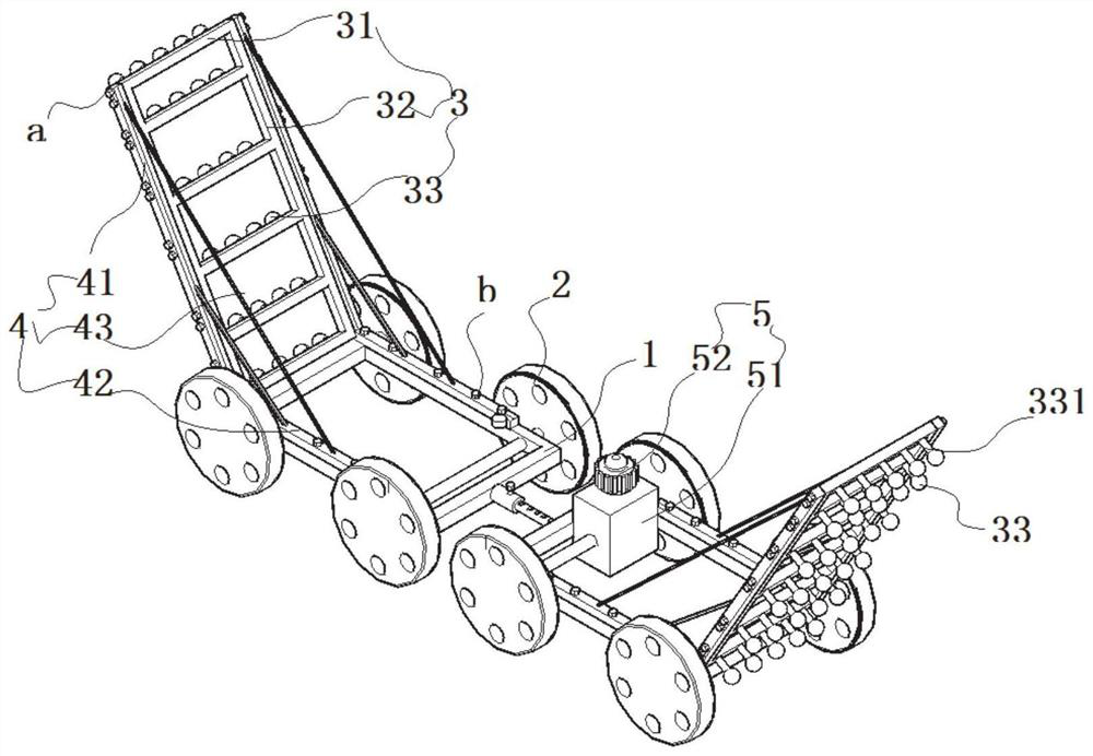
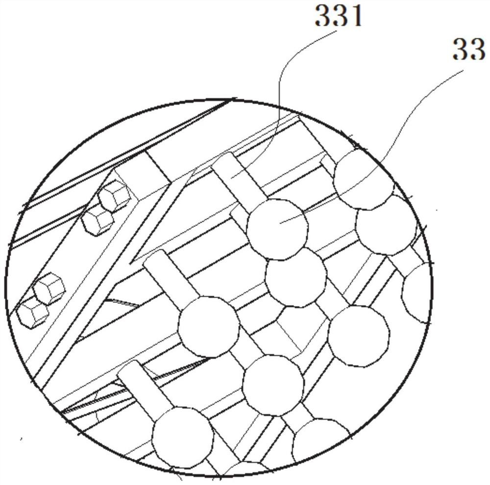
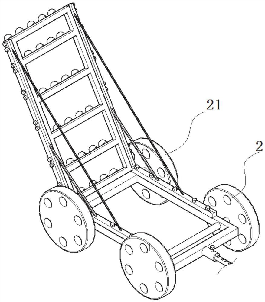
[0045] Such as Figure 1-8 As shown, a substation monitoring device includes monitoring components arranged symmetrically on the left and right sides;

[0046] The monitoring components are connected by telescopic elements 6;

[0047] The monitoring components all include a rectangular rack bar 1, and the front and rear sides of the top of the rectangular rack bar 1 are equipped with suspensions 4 arranged at intervals before and after;

[0048] The suspension 4 includes a horizontal portion 42 assembled on the rectangular frame rod 1, and the left side of the horizontal portion 42 is inclined upwardly provided with an inclined portion 41;

[0049] A monitoring component 3 is installed between the inclined parts 41, and the monitoring part 3 includes a rectangular mounting rod 32 assembled on the inclined part 41;

[0050] The front and rear sides of the rectangular mounting frame rod 32 are all inclined downwardly arranged...

Embodiment 2

[0065] Embodiment 2 substation monitoring method

[0066] Such as Figure 1-8 As shown, a substation monitoring device includes monitoring components arranged symmetrically on the left and right sides;

[0067] The monitoring components are connected by telescopic elements 6;

[0068]The monitoring components all include a rectangular rack bar 1, and the front and rear sides of the top of the rectangular rack bar 1 are equipped with suspensions 4 arranged at intervals before and after;

[0069] The suspension 4 includes a horizontal portion 42 assembled on the rectangular frame rod 1, and the left side of the horizontal portion 42 is inclined upwardly provided with an inclined portion 41;

[0070] A monitoring component 3 is installed between the inclined parts 41, and the monitoring part 3 includes a rectangular mounting rod 32 assembled on the inclined part 41;

[0071] The front and rear sides of the rectangular mounting frame rod 32 are all inclined downwardly arranged ...


PUM


Abstract

The invention discloses a transformer substation monitoring device, and the device comprises monitoring assemblies symmetrically arranged on the left side and the right side; the monitoring assembliesare connected through telescopic pieces, each monitoring assembly comprises a rectangular rack rod, suspensions arranged at intervals front and back are assembled on the front side and the rear sideof the top of each rectangular rack rod, and each suspension comprises a horizontal part assembled on the corresponding rectangular rack rod; inclined parts are obliquely arranged on the left side ofthe horizontal part upwards, a monitoring part is assembled between the inclined parts, the monitoring part comprises a rectangular mounting frame rod assembled on the inclined parts, traction rods obliquely arranged on the front side and the rear side of the rectangular mounting frame rod downwards, and a plurality of sensor probes are fixedly connected to the rectangular mounting frame rod; anda driving wheel part is assembled on the rectangular rack rod. By adopting the device part design, the transformer substation working equipment can be efficiently and accurately monitored, and the device part design replaces manual inspection monitoring, so that the safety working characteristic of the transformer substation working equipment is effectively improved.

Description

technical field [0001] The invention relates to the field of substation monitoring devices, in particular to a substation monitoring device. Background technique [0002] A substation is a place in a power system that transforms voltage and current, receives electric energy and distributes electric energy. The substation in the power plant is a step-up substation, whose function is to boost the electric energy generated by the generator and feed it to the high-voltage grid. [0003] The substation mainly includes [0004] one-time equipment: [0005] Primary equipment refers to equipment that directly produces, transmits, distributes and uses electric energy, mainly including transformers, high-voltage circuit breakers, disconnectors, busbars, lightning arresters, capacitors, reactors, etc. [0006] Secondary equipment: [0007] The secondary equipment of the substation refers to the equipment that measures, monitors, controls and protects the operating conditions of the...

Claims


Application Information

Patent Timeline
IPC IPC(8): H02B3/00
CPCH02B3/00
Inventor 高琛高祥银李来春邵玉峰张靳
Owner LIANGSHAN POWER SUPPLY CO OF STATE GRID SHANDONG ELECTRIC POWER CO
Learn More