Intelligent bearing monitoring system and method based on transient speed

A monitoring system and bearing technology, applied in mechanical bearing testing, linear/angular velocity measurement, velocity/acceleration/impact measurement, etc., can solve the problems of fixed sampling frequency, low conversion accuracy, unfavorable application, etc.

Active Publication Date: 2016-06-08
CHONGQING UNIV +1
View PDF10 Cites 0 Cited by
  • Summary
  • Abstract
  • Description
  • Claims
  • Application Information

AI Technical Summary

Problems solved by technology

Therefore, it is necessary to realize the smooth transformation of the non-stationary signal. Although the existing encoder-based and tachometer-based equiangular sampling methods realize the smooth transformation of the signal, the sampling frequency of the former is fixed and low, and the conversion accuracy of the latter is low. low, and the installation of both acquisition devices has relatively large limitations, which is not conducive to practical application

Method used

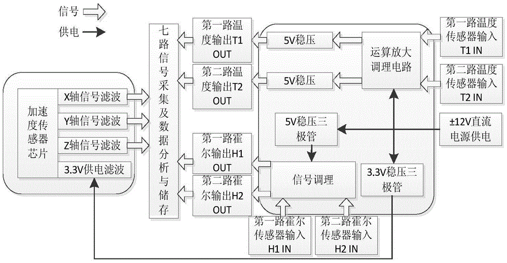
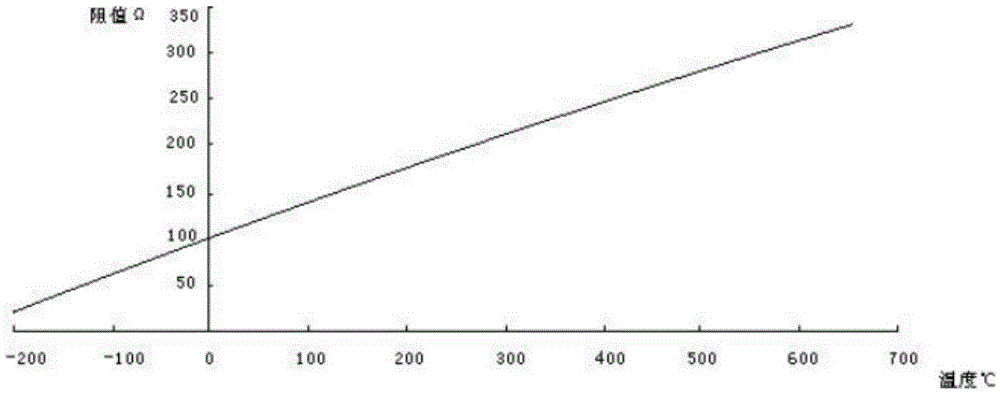
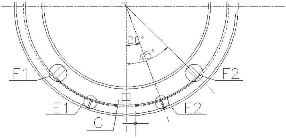

Image

  • Intelligent bearing monitoring system and method based on transient speed
  • Intelligent bearing monitoring system and method based on transient speed
  • Intelligent bearing monitoring system and method based on transient speed

Examples


Embodiment Construction

[0061] Embodiments of the present invention are described in detail below, examples of which are shown in the drawings, wherein the same or similar reference numerals designate the same or similar elements or elements having the same or similar functions throughout. The embodiments described below by referring to the figures are exemplary only for explaining the present invention and should not be construed as limiting the present invention.

[0062] In describing the present invention, it should be understood that the terms "longitudinal", "transverse", "upper", "lower", "front", "rear", "left", "right", "vertical", The orientation or positional relationship indicated by "horizontal", "top", "bottom", "inner", "outer", etc. are based on the orientation or positional relationship shown in the drawings, and are only for the convenience of describing the present invention and simplifying the description, rather than Nothing indicating or implying that a referenced device or elem...


PUM


Abstract

The monitoring system of the present invention is composed of an integrated signal conditioning circuit board and a vibration acceleration sensor circuit board, which can realize signal conditioning and signal output of two speed sensors, two temperature sensors and one triaxial vibration acceleration signal. Process the collected acceleration signal and pulse signal to obtain the angular domain and time domain stable signal and instantaneous speed. There are four main steps: Step 1. Divide the bearing into several areas in the circumferential direction and install the magnetic steel. The magnetic steel rotates with the bearing. The Hall sensor obtains the pulse signal; step 2, calculate the time difference between adjacent pulses, and obtain the instantaneous rotational speed of the bearing; step 3, obtain a time domain stable signal by equal interpolation of the time domain signals collected in each area; step 4 , according to the relation of speed variation, the time domain signal is interpolated and resampled to obtain the angle domain stationary signal. The present invention generally realizes the real-time adjustment and monitoring of the three dynamic parameters of rotation speed, temperature and vibration acceleration.

Description

technical field [0001] The invention relates to the field of mechanical automation, in particular to an intelligent bearing monitoring system and method based on transient speed. Background technique [0002] High-speed trains and urban rail transit are a symbol of a country's advanced technology, and their reliability and safety are directly related to the personal and property safety of the people and the image of the country. Smart bearings have broken through the traditional bearing condition monitoring and diagnosis methods, and are a key technology applied to high-speed trains. At present, this technology is monopolized and blocked by foreign countries. Therefore, the study of smart bearings has great social and economic value. The concept of intelligent bearing is to integrate a variety of sensors to realize real-time monitoring and fault diagnosis of various dynamic parameters of the bearing. The original signal of the composite sensor is not necessarily the commonl...

Claims


Application Information

Patent Timeline
Patent Type & Authority Patents(China)
IPC IPC(8): G01M13/04G01P3/481
Inventor 邵毅敏叶维军王利明叶军陈国钦牛青波杨与东刘飞
Owner CHONGQING UNIV
Why Eureka
Try Eureka