Self-pressurization type spraying device for plant protection unmanned aerial vehicle
A technology of plant protection drones and spraying devices, which is applied in the direction of launching devices, devices for catching or killing insects, mixers with rotating stirring devices, etc., which can solve problems such as inability to spray, poor spraying effect, and waste of liquid medicine. Achieve the effects of improving mixing efficiency, reducing production costs, and increasing spraying range
- Summary
- Abstract
- Description
- Claims
- Application Information
AI Technical Summary
Problems solved by technology
Method used
Image
Examples
Embodiment 1
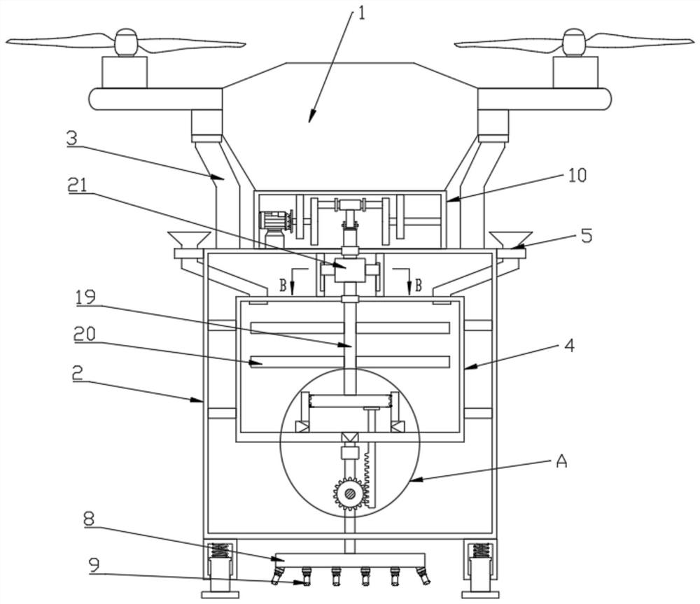
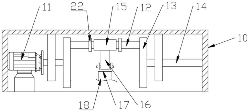
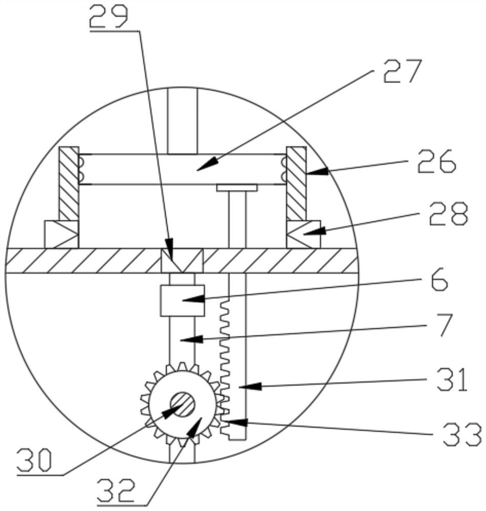
[0027] see Figure 1-7 , a self-pressurized spraying device for plant protection drones, including a drone body 1 and an installation box 2 located below the drone, characterized in that the drone body 1 is connected to the installation via a connecting rod 3 The box 2 is fixedly connected, the inside of the installation box 2 is connected with a water tank 4 through a reinforcing rod, and the side of the installation box 2 is fixedly provided with a water inlet 5, and the water inlet 5 communicates with the water tank 4 through a pipeline, and the installation box 2 A stirring mechanism is provided inside, and a pressurizing mechanism connected to the stirring mechanism is provided in the water tank 4. The bottom surface of the pressurizing mechanism is connected with a hollow rod 7 communicating with it through a rotary joint 6, and the bottom of the hollow rod 7 is connected to the The bottom surface of the installation box 2 is rotatably connected, and the end of the rod b...
Embodiment 2
[0035] This embodiment expands the functions on the basis of Embodiment 1, specifically:
[0036] Described driving mechanism comprises the 3rd rotating shaft 30, driving rod 31, driving gear 32, first bevel gear 34 and the second bevel gear 35, and described 3rd rotating shaft 30 rotations are arranged between water tank 4 bottom surface and installation box 2, and The third rotating shaft 30 is fixedly provided with a driving gear 32, the top of the driving rod 31 penetrates the bottom surface of the water tank 4 and is fixedly connected with the piston block 27, and the driving rod 31 is provided with a rack 33 meshing with the driving gear 32, so The first bevel gear 34 is sleeved on the hollow rod 7, and a ratchet pawl structure that only allows the hollow rod 7 to rotate in one direction is provided between the first bevel gear 34 and the hollow rod 7, and the third rotating shaft 30 is provided with There is a second bevel gear 35 that meshes with the first bevel gear 3...
PUM
 Abstract
Description
Claims
Application Information
 - R&D
- Intellectual Property
- Life Sciences
- Materials
- Tech Scout
- Unparalleled Data Quality
- Higher Quality Content
- 60% Fewer Hallucinations
Browse by: Latest US Patents, China's latest patents, Technical Efficacy Thesaurus, Application Domain, Technology Topic, Popular Technical Reports.
© 2025 PatSnap. All rights reserved.Legal|Privacy policy|Modern Slavery Act Transparency Statement|Sitemap|About US| Contact US: help@patsnap.com


