
Gas phase distribution device and catalytic reaction equipment

A gas phase distribution and catalyst technology, which is applied in the chemical industry to avoid pulverization and deactivation, equalize pressure, and reduce the difficulty of replacement.

Pending Publication Date: 2021-02-12
JIANGSU SINORGCHEM TECH CO LTD
View PDF0 Cites 0 Cited by
  • Summary
  • Abstract
  • Description
  • Claims
  • Application Information

AI Technical Summary

Problems solved by technology

[0004] The embodiment of the present application provides a gas phase distribution device and catalytic reaction equipment to solve or alleviate one or more technical problems in the prior art

Method used


Image

  • Gas phase distribution device and catalytic reaction equipment
  • Gas phase distribution device and catalytic reaction equipment
  • Gas phase distribution device and catalytic reaction equipment

Examples


Embodiment Construction

[0025] In the following, only some exemplary embodiments are briefly described. As those skilled in the art would realize, the described embodiments may be modified in various different ways, all without departing from the spirit or scope of the present application. Accordingly, the drawings and descriptions are to be regarded as illustrative in nature and not restrictive.

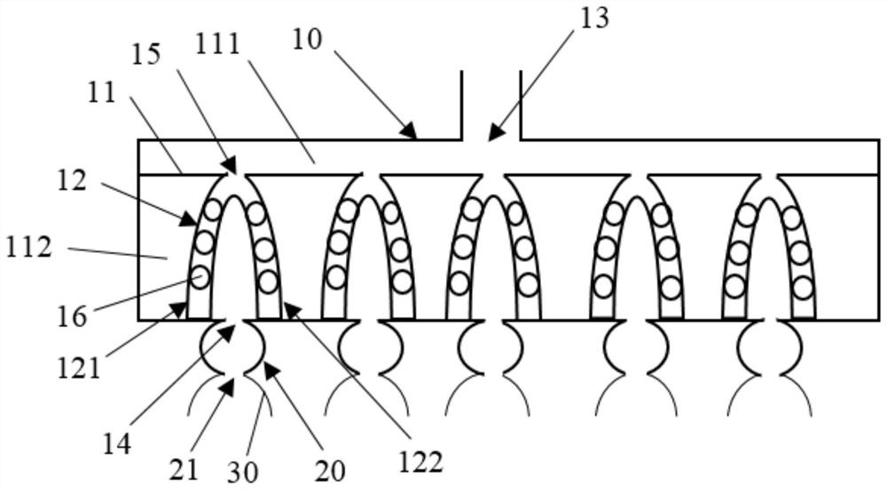
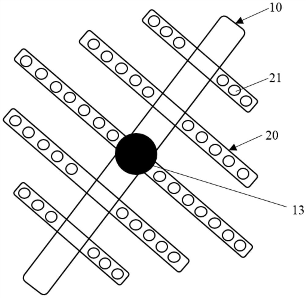
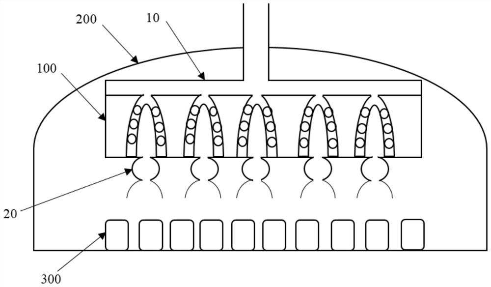
[0026] figure 1 It is a schematic structural diagram of a gas phase distribution device in an embodiment of the present application. Such as figure 1 As shown, the gas phase distribution device of the embodiment of the present application includes a main pipeline 10 , and the main pipeline 10 includes a partition plate 11 and a damper 12 . The partition plate 11 is disposed in the inner cavity of the main pipeline 10 , and the partition plate 11 divides the inner cavity of the main pipeline 10 into a first cavity 111 and a second cavity 112 . The wall of the main pipeline 10 is provided with a material...


PUM


Abstract

The embodiment of the invention provides a gas phase distribution device and catalytic reaction equipment. The gas phase distribution device comprises a main pipeline, the main pipeline comprises a partition plate arranged in an inner cavity of the main pipeline so as to divide the inner cavity of the main pipeline into a first cavity and a second cavity, the main pipeline is provided with a feedport communicated with the first cavity and a discharge port communicated with the second cavity; a flow slowing device, located in the second cavity, a first through opening corresponding to the flowslowing device is formed in the partition plate, an inner cavity of the flow slowing device is communicated with the first cavity through the first through opening, at least two second through openings are formed in the cavity wall of the flow slowing device, and the inner cavity of the flow slowing device is communicated with the second inner cavity through the at least two second through openings. According to the gas-phase distribution device, the vaporized materials can be fully shunted and buffered, so that the vaporized materials sprayed from the gas-phase distribution device are uniform and balanced in pressure, the vaporized materials are prevented from forming bias flow, the vaporized materials are in full contact with a catalyst, and the catalytic reaction conversion rate is increased.

Description

technical field [0001] The application relates to the technical field of chemical industry, in particular to a gas phase distribution device and catalytic reaction equipment. Background technique [0002] In the catalytic reaction process of chemical production, after the heated and vaporized material enters the head of the converter, the vaporized material penetrates into the catalyst in the tube, and under the action of heat and power, the material and the catalyst are in close contact to complete the catalysis. [0003] However, in actual production, the vaporized material cannot fully contact the catalyst on the surface of the tube, and the material is in close contact with the catalyst facing the tube, while the catalyst in the surrounding tubes has less contact with the material, and the material forms a bias flow in the tube , so that the intermediate catalyst is pulverized and deactivated quickly, which makes it more difficult to replace the catalyst. Contents of t...

Claims


Application Information

Patent Timeline
Patent Type & Authority Applications(China)
IPC IPC(8): B01J8/06B01J8/02
CPCB01J8/0278B01J8/06
Inventor 郑夫忠李文涛霍强谢磊毛安吉
Owner JIANGSU SINORGCHEM TECH CO LTD
Learn More