Automatic visual detection device for regulator

A visual inspection device and regulator technology, applied in sorting and other directions, can solve the problems of low efficiency, uneven quality, and large error in manual inspection of the regulator, and achieve high detection efficiency, guaranteed yield, and high accuracy. Effect

Inactive Publication Date: 2021-02-12
CHONGQING YUANCHUANG PHOTOELECTRIC TECH CO LTD
View PDF8 Cites 1 Cited by
  • Summary
  • Abstract
  • Description
  • Claims
  • Application Information

AI Technical Summary

Problems solved by technology

[0004] Aiming at the technical problems of large errors, low efficiency, and uneven quality of manual detection of regulators, the present invention provides an automatic visual detection device for regulators, which can complete automatic detection of regulators with high efficiency and high accuracy

Method used


Image

  • Automatic visual detection device for regulator
  • Automatic visual detection device for regulator
  • Automatic visual detection device for regulator

Examples


Embodiment 1

[0054] The product of this embodiment is a military regulator.

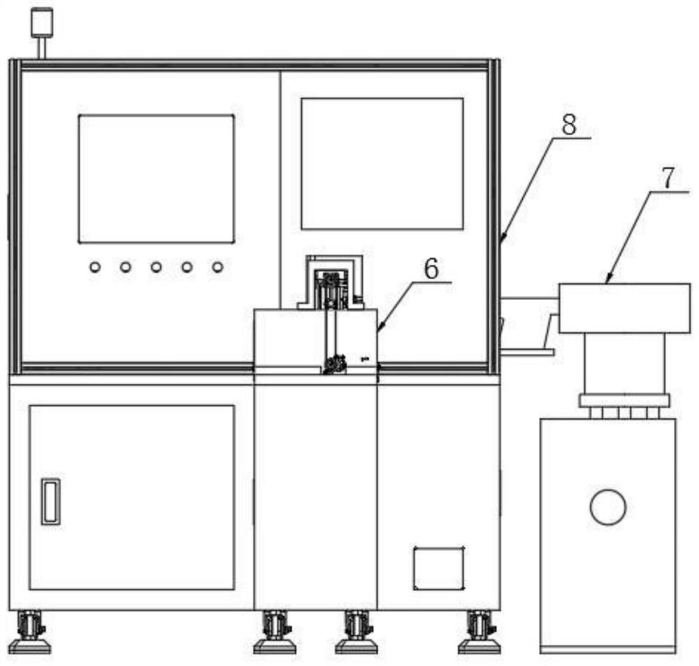
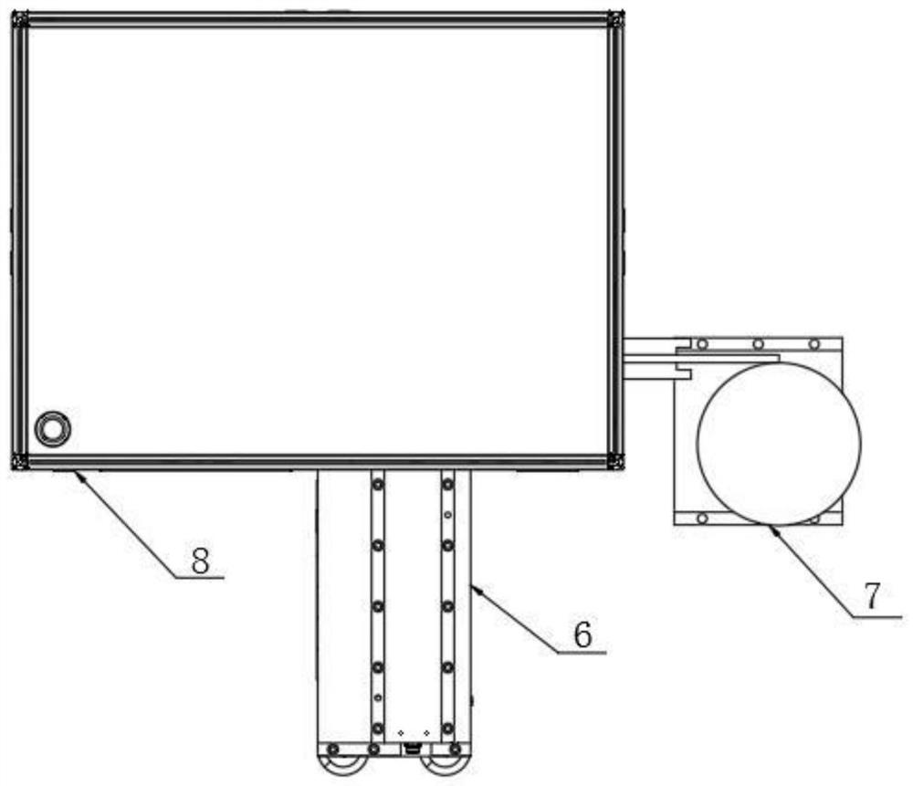
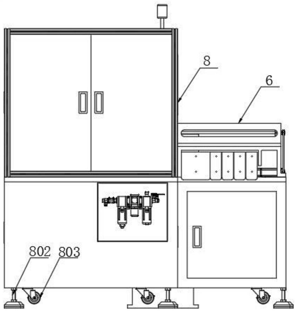
[0055] refer to Figure 1 to Figure 13 , the automatic visual inspection device for the regulator of the present invention, comprising:

[0056] A cabinet 8, a bottom plate 801 is arranged horizontally in the cabinet;

[0057] The feeding mechanism 7 is arranged on the side of the cabinet 8, and is used for feeding and transporting products;

[0058] The first detection station 1 is arranged on the bottom plate 801 and is used to detect whether the characters on the bottom of the product are correct;

[0059] The second detection station 2 is arranged on the bottom plate 801 and is used to detect whether there is a scratch in the annular groove on the surface of the product;

[0060] The third detection station 3 is arranged on the bottom plate 801, and is used to detect whether the aperture of the side hole on the side of the product is correct;

[0061] The fourth detection station 4 is arranged on the bott...

Embodiment 2

[0073] refer to Figure 11, on the basis of Embodiment 1, this embodiment is provided with a marking mechanism on the side of the blanking mechanism for marking on the product; the marking mechanism includes a horizontally arranged pen-shaped cylinder 901, the movable end of the pen-shaped cylinder A hoop 902 is provided, and a marking pen (not shown in the figure) is fixed on the hoop. When the detected product is unqualified, the pen-shaped air cylinder stretches out to drive the marking pen to move. With the movement of the product, the marking pen makes a mark on the product, which is convenient for subsequent operators to identify.

Embodiment 3

[0075] On the basis of Embodiment 1, this embodiment is provided with a first fine-tuning mechanism and a first adjustment mechanism on the first camera; a second fine-tuning mechanism and a second adjustment mechanism are provided on the second camera; A third fine-tuning mechanism and a third adjusting mechanism are set; a fourth fine-tuning mechanism and a fourth adjusting mechanism are set on the fourth camera; a fifth fine-tuning mechanism and a fifth adjusting mechanism are set on the fifth camera;

[0076] The structures and principles of the first fine-tuning mechanism, the second fine-tuning mechanism, the third fine-tuning mechanism, the fourth fine-tuning mechanism and the fifth fine-tuning mechanism are the same; the first regulating mechanism, the second regulating mechanism, the third regulating mechanism, the fourth regulating mechanism and The structure and principle of the fifth regulating mechanism are the same.

[0077] refer to Figure 13 , taking the four...


PUM


Abstract

The invention discloses an automatic visual detection device for a regulator. The automatic visual detection device for the regulator comprises a cabinet, a feeding mechanism and a discharging mechanism, wherein a bottom plate is horizontally arranged in the cabinet; a first detection station, a second detection station, a third detection station, a fourth detection station and a fifth detection station are arranged on the bottom plate; the first detection station comprises a feeding bracket; a feeding screw rod is horizontally arranged on the feeding bracket; a first motor is arranged at theend part of the feeding screw rod; a first light source is arranged on the bottom plate below a pneumatic claw; and a first camera is arranged below the first light source. According to the automaticvisual detection device for the regulator provided by the invention, automatic feeding and discharging of a product to be detected can be completed through the feeding mechanism and the discharging mechanism, and five parameters of characters, an annular groove, the hole diameter of a side hole, a chamfer and the hole diameter of an upper end hole of the product can be automatically detected through the five detection stations arranged in the cabinet; traditional manual detection is replaced, and the advantages of high detection efficiency and high accuracy are achieved; and meanwhile, the manual labor intensity and the production cost are also reduced, and the yield of products is ensured.

Description

technical field [0001] The invention relates to the technical field of automatic equipment detection, in particular to an automatic visual detection device for regulators. Background technique [0002] The regulator compares the measured value of the production process parameters with the given value, and after obtaining the deviation, generates an output signal according to a certain regulation law to push the actuator to eliminate the deviation, so that the parameter remains near the given value or changes according to a predetermined law controller. [0003] After the regulator is produced, it needs to be inspected for quality. The quality inspection includes testing the characters on the surface of the regulator, whether there are scratches in the annular groove, the aperture of the side hole, the chamfer, the aperture of the upper hole and other parameters. The traditional detection method is through manual and detection tools, using visual inspection and instrument me...

Claims


Application Information

Patent Timeline
Patent Type & Authority Applications(China)
IPC IPC(8): B07C5/10B07C5/34B07C5/38
CPCB07C5/10B07C5/34B07C5/3412B07C5/38
Inventor 李志远耿世慧李熙春
Owner CHONGQING YUANCHUANG PHOTOELECTRIC TECH CO LTD
Why Eureka
Try Eureka