Steel block cutting and polishing device for manufacturing high-end equipment

A technology of equipment and steel blocks, which is applied in the field of steel block segmentation and polishing equipment for high-end equipment manufacturing, can solve problems such as low efficiency and inability to guarantee the cutting effect of steel blocks, and achieve the effect of improving work efficiency and ensuring personal safety

Active Publication Date: 2021-02-12
广州幸永科技有限公司
View PDF9 Cites 6 Cited by
  • Summary
  • Abstract
  • Description
  • Claims
  • Application Information

AI Technical Summary

Problems solved by technology

[0005] In order to overcome the disadvantages that the current manual hand-held electric saw cuts the steel block, it is easy to cut the steel block obliquely, the cutting effect of the steel block cannot be guaranteed, and the cut steel block needs to be manually polished separately, which is inefficient. The technical problem to be solved is to provide a steel block splitting and polishing equipment for high-end equipment manufacturing with good cutting effect, guaranteed steel block product quality and high polishing efficiency

Method used


Image

  • Steel block cutting and polishing device for manufacturing high-end equipment
  • Steel block cutting and polishing device for manufacturing high-end equipment
  • Steel block cutting and polishing device for manufacturing high-end equipment

Examples


Embodiment 1

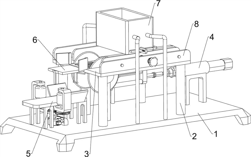
[0028] A high-end equipment manufacturing steel block split polishing equipment, such as Figure 1 to Figure 4 As shown, it includes a base 1, a support column 2, a cutting assembly 3, a propulsion mechanism 4 and a grinding mechanism 5, a support column 2 is installed on the top of the base 1, a cutting assembly 3 is installed between the support column 2 and the base 1, and a cutting assembly 3 is installed on the top of the base 1. Propelling mechanism 4 is installed on the right side, and grinding mechanism 5 is installed on the left side of base 1 top.

[0029] The cutting assembly 3 includes a workbench 31, a fixed mount 32, a cutting machine 33 and a waste partition 34. The top of the support column 2 is connected with a workbench 31, and the front and rear sides in the middle of the top of the base 1 are connected with a fixed mount 32. Cutting machine 33 is all installed on the fixed mount 32 of side, and the saw blade of cutting machine 33 penetrates workbench 31 top...

Embodiment 2

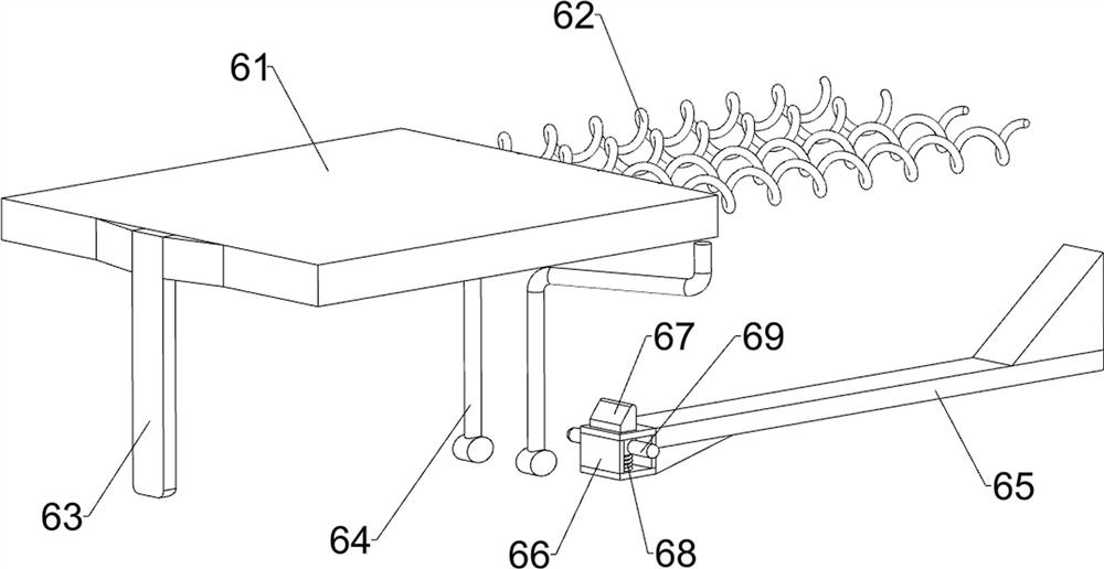
[0034] On the basis of Example 1, such as Figure 5As shown, a movable pallet mechanism 6 is also included, and the movable pallet mechanism 6 includes a sliding pallet 61, a first return spring 62, a fixed pull plate 63, a top block frame 64, a connecting rod 65, a first guide sleeve 66, Block 67, the second back-moving spring 68 and protruding rod 69, the left end of workbench 31 has chute, is connected with sliding supporting plate 61 slidingly in the chute, is connected with the second between sliding supporting plate 61 and the chute inwall. One back-moving spring 62, the left end bottom of sliding supporting plate 61 is connected with fixed pull plate 63, and the left side bottom of workbench 31 is connected with two jacking frame 64, and two jacking frame 64 are symmetrically arranged front and back, special-shaped connecting rod 43 The middle part of the left end of the connecting rod 65 is fixedly connected with the connecting rod 65, and the left end of the connectin...

Embodiment 3

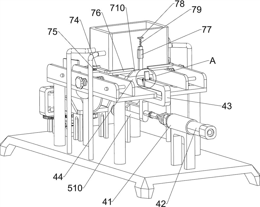
[0037] On the basis of Example 2, such as figure 2 , image 3 and Figure 6 As shown, also includes material storage mechanism 7, and material storage mechanism 7 includes support frame 71, material storage box 72, sliding partition 73, guide block 74, the 3rd return spring 75, ejector rod 76, the second guide sleeve 77 , fixed block 78, the 4th back-moving spring 79, wedge-shaped block frame 710, connecting block 711, scroll spring 712 and L-shaped wedge-shaped block 713, the front and rear both sides in the middle of base 1 top are all connected with support frame 71, the support of both sides The storage box 72 is connected between the top of the frame 71, and the front and rear sides of the bottom of the storage box 72 are slidably connected with a sliding partition 73, and the front and rear sides of the bottom of the storage box 72 are connected with a guide block 74. 74 and the sliding partition 73 are connected with a third return spring 75, the right side of the sl...


PUM


Abstract

The invention relates to a cutting and polishing device, and particularly relates to a steel block cutting and polishing device for manufacturing high-end equipment. The steel block cutting and polishing device for manufacturing the high-end equipment is good in cutting effect, capable of guaranteeing the quality of steel block products and high in polishing efficiency. The steel block cutting andpolishing device for manufacturing the high-end equipment comprises a base, a cutting assembly, a pushing mechanism and a polishing mechanism, wherein a supporting column is installed on the base, the cutting assembly is connected between the supporting column and the base, the pushing mechanism is connected to one side of the top of the base, and the polishing mechanism is connected to the otherside of the top of the base. According to the steel block cutting and polishing device for manufacturing the high-end equipment, steel blocks can be cut through cooperation of the cutting assembly and the pushing mechanism, the cut edges are polished under the action of the polishing mechanism, and therefore the cut portions are smoother.

Description

technical field [0001] The invention relates to a split polishing device, in particular to a split polishing device for steel blocks used in high-end equipment manufacturing. Background technique [0002] A large amount of steel is usually used in the manufacture of high-end equipment, especially the larger steel blocks are used more frequently. Large steel blocks need to be cut, and the cut parts need to be polished. Currently, the cutting of steel blocks is usually Fix the steel block with a vise, and cut it manually with a hand-held electric saw. Such manual cutting is easy to cut the steel block obliquely, and the cutting effect of the steel block cannot be guaranteed. Moreover, the cut steel block needs to be manually polished separately, and the efficiency is high. low. [0003] Therefore, how to design a high-end equipment manufacturing steel ingot splitting and polishing equipment with good cutting effect, guaranteed steel ingot product quality and high polishing ef...

Claims


Application Information

Patent Timeline
IPC IPC(8): B23P23/04B23Q7/00
CPCB23P23/04B23Q7/00
Inventor 杨苏原
Owner 广州幸永科技有限公司
Why Eureka
Try Eureka