Photovoltaic panel carrying tool

A photovoltaic panel and porter technology, applied in the field of photovoltaic panel handling tooling, can solve problems such as low work efficiency, and achieve the effects of simple structure, improved stability, and reduced damage rate

Inactive Publication Date: 2021-02-12
PINGGAO GRP
View PDF5 Cites 4 Cited by
  • Summary
  • Abstract
  • Description
  • Claims
  • Application Information

AI Technical Summary

Problems solved by technology

[0003] The purpose of the present invention is to provide a photovoltaic panel handling tool to solve the technica...

Method used


Image

  • Photovoltaic panel carrying tool
  • Photovoltaic panel carrying tool
  • Photovoltaic panel carrying tool

Examples


Embodiment 1

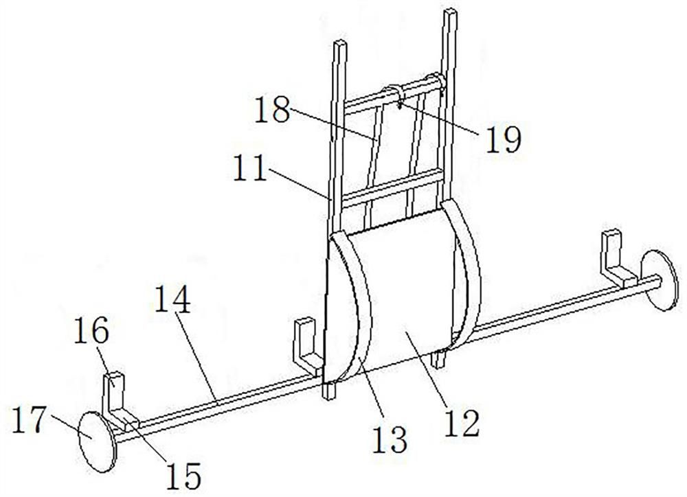
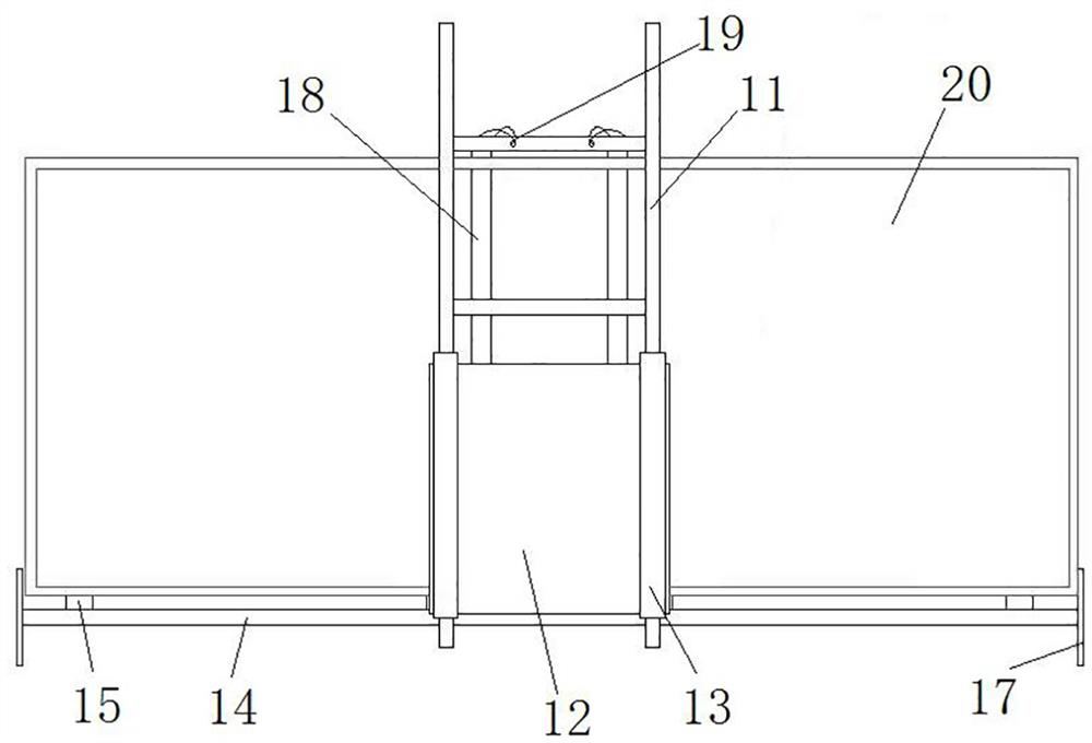
[0038] Such as figure 1 and figure 2 As shown, the photovoltaic panel handling equipment includes a back frame 11, the back frame 11 extends in the up and down direction, the back frame 11 includes two vertical bars and three horizontal bars, and the three horizontal bars are fixedly connected between the two vertical bars by bolts, to form a frame structure. In this embodiment, the height of the pole is greater than the height of the photovoltaic panel 20 , so that the back frame 11 is limited to the photovoltaic panel 20 in the forward direction by the frame of the photovoltaic panel 20 . Wherein, the top cross bar is provided with a hanging ring, and the hanging ring is used for the hook 19 to hang.

[0039] Such as figure 1 and image 3 As shown, the lower front side of the back frame 11 is fixed with a back plate 12 by bolts, and the front side of the back frame 11 is also provided with a strap 13, two straps 13 are provided, and the two straps 13 correspond to the l...

Embodiment 2

[0050] The difference between this embodiment and Embodiment 1 is that in Embodiment 1, an L-shaped bracket is provided on the support rod 14, and the L-shaped bracket includes a horizontal section 15 and a vertical section 16, and the horizontal section 15 is used to support the photovoltaic panel 20 , the vertical section 16 is used to limit the photovoltaic panel 20 in the backward direction. In this embodiment, only a horizontal section is provided on the support rod, and the photovoltaic panel is limited in the backward direction by an elastic fixing belt.

Embodiment 3

[0052] The difference between this embodiment and Embodiment 1 is that in Embodiment 1, the support frame includes a support rod 14 extending along the left and right directions, and a plurality of L-shaped brackets are arranged on the support rod 14 . In this embodiment, the support frame is an L-shaped frame, and the L-shaped frame extends along the left and right directions. The L-shaped frame includes a horizontal section and a vertical section. direction upper limit.


PUM


Abstract

The invention relates to a photovoltaic panel carrying tool. The photovoltaic panel carrying tool comprises a back frame, straps, a supporting frame and a fixing band, wherein the back frame is arranged in the vertical direction, a back plate is fixedly arranged on the front side of the back frame, the straps are arranged on the front side of the back frame and correspond to the back plate, the supporting frame are arranged on the lower portion of the back frame, the supporting frame is provided with a supporting part and a limiting part, the supporting part is used for supporting a photovoltaic panel, the limiting part is used for limiting the photovoltaic panel in the left-right direction, and the fixing band is arranged on the rear side of the back frame and used for pressing the photovoltaic panel on the supporting part on the back frame. Due to the fact that when the photovoltaic panel carrying tool is used for fixing the photovoltaic panel, the stress point of the photovoltaic panel is located on the frame of the photovoltaic panel, a panel body of the photovoltaic panel cannot bear larger external force, it is guaranteed that the photovoltaic panel is not prone to being damaged in a carrying process, the damage rate of the photovoltaic panel is reduced, besides, the photovoltaic panel carrying tool can be carried by a single person, and can carry a plurality of photovoltaic panels at the same time, so that the carrying efficiency is improved.

Description

technical field [0001] The invention relates to a photovoltaic panel handling tool. Background technique [0002] Photovoltaic panels are an important component in photovoltaic power generation projects. Due to the complex terrain and wide construction area where photovoltaic power generation projects are located, most photovoltaic panels are first transported to the construction center by vehicle, and then manually transported to the construction site for installation. At present, the usual method is to carry photovoltaic panels by two people. This method of transportation has the following disadvantages: first, two people are required to cooperate to carry photovoltaic panels, which consumes more moving personnel and lower work efficiency; second, two people are required to operate Highly coordinated and difficult to cooperate, it is easy to cause damage or cracks to the photovoltaic panels during the handling process. Contents of the invention [0003] The purpose of t...

Claims


Application Information

Patent Timeline
IPC IPC(8): B65G7/12
CPCB65G7/12B65G2201/022
Inventor 李振坡罗朋李黎明王琨李志刚宋碧昊张跃进张涛张欣鹏
Owner PINGGAO GRP
Why Eureka
Try Eureka