Supercharge Your Innovation With Domain-Expert AI Agents!

Lifting system applied to lifting and mounting of main tower steel truss

A lifting system and steel truss technology, applied in safety devices, bridge erection/assembly, transportation and packaging, etc., can solve the problems of bulky main tower steel truss, damage to the stability of the bridge main body, low efficiency, etc., to ensure construction efficiency and personal safety, improve the matching accuracy and load performance, and improve the effect of motion stability

Pending Publication Date: 2021-02-12
CHINA RAILWAY JIUJIANG BRIDGE ENG +1
View PDF0 Cites 1 Cited by
  • Summary
  • Abstract
  • Description
  • Claims
  • Application Information

AI Technical Summary

Problems solved by technology

For the installation of this kind of main tower steel truss, the existing technology often carries out the operation by segmental lifting or overall lifting. If segmental lifting is adopted, on-site welding must be carried out, which has the disadvantages of low efficiency, cumbersome procedures, time-consuming and laborious Shortcomings, and the post-welding stress deformation of on-site welding will also cause the shape of the overall steel truss to be distorted, destroying the stability of the main body of the bridge; if the qualified steel truss is pre-fabricated and the entire section is hoisted, the volume of the entire main tower steel truss is too large , when the position of the installation interface needs to be accurately positioned at the end of hoisting, once a size deviation occurs, the overly heavy main tower steel truss must be moved and adjusted, and the operation is very troublesome; moreover, the main tower steel truss It is easy to shake during the process of transportation and adjustment. Even if the wind blowing near the bridge causes it to be in a slight shaking state, it is difficult for the constructor to perform installation and docking operations on it during the shaking process, and there are problems during the operation. big job hazard

Method used


Image

  • Lifting system applied to lifting and mounting of main tower steel truss
  • Lifting system applied to lifting and mounting of main tower steel truss
  • Lifting system applied to lifting and mounting of main tower steel truss

Examples


Embodiment Construction

[0029] The present invention will be described in further detail below in conjunction with the accompanying drawings and embodiments.

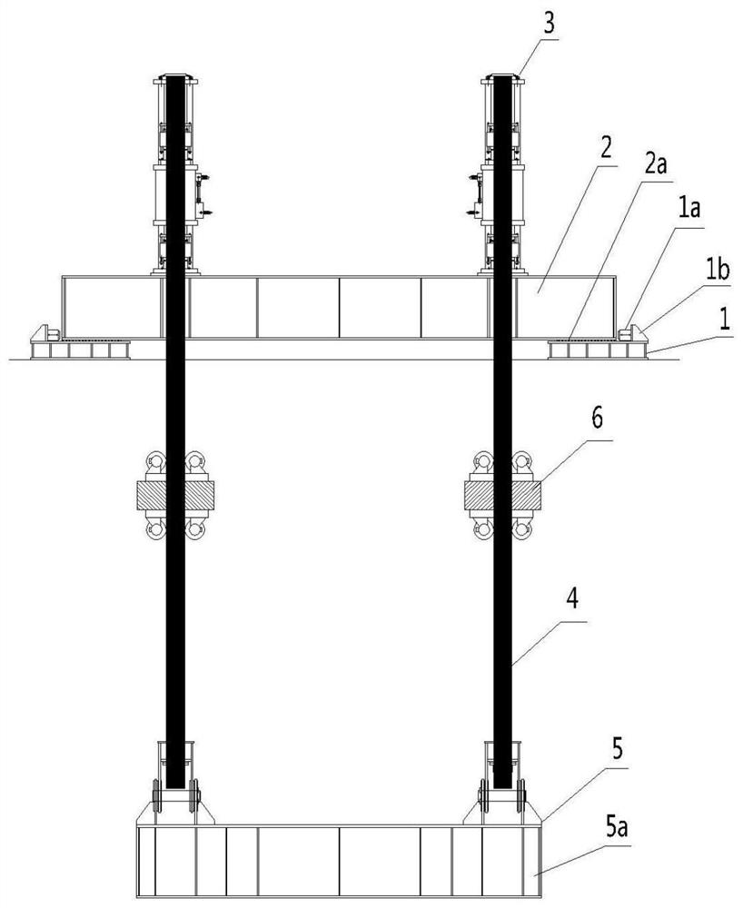
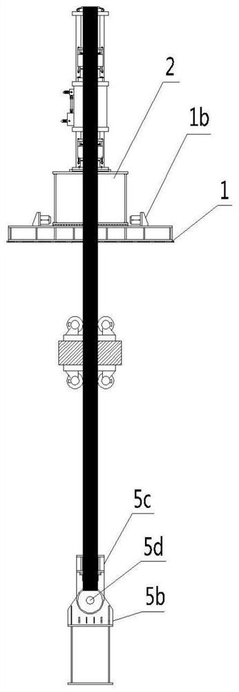
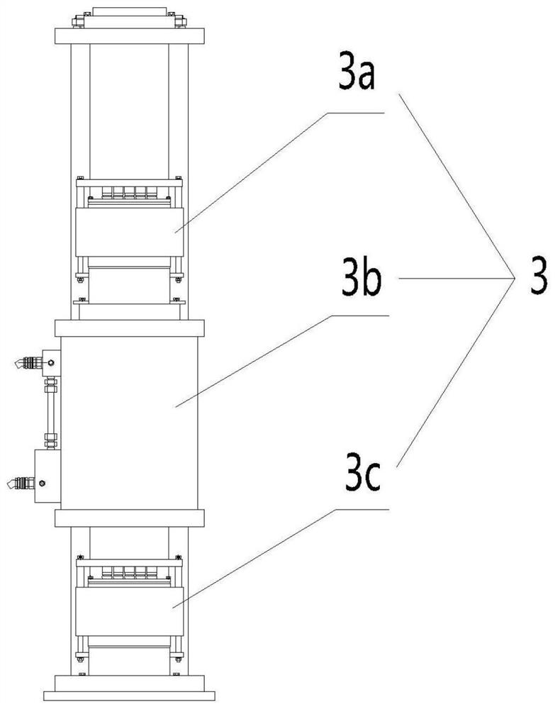
[0030] Such as Figure 1-5As shown, a lifting system applied to the lifting and installation of the main tower steel truss, including two pad beams 1, main longitudinal beams 2, two through-hole jacks 3, two steel strands 4, spreaders 5, two Vibration absorbing mechanism6. Wherein, the two pad beams 1 are respectively arranged in the front and rear end areas of the top surface of the concrete main tower in a symmetrical manner. A lubricating plate 2a made of polytetrafluoroethylene is provided at the bonding parts, so that the main longitudinal girder 2 can fit the lubricating plate 2a to move in the horizontal direction; the upper end surface of the pad beam 1 is provided with a plurality of longitudinal movement jacks 1a, a plurality of transverse movement jacks 1b, a plurality of reaction force seats 1c, the fuselages of a plurality of sa...


PUM


Abstract

The invention provides a lifting system applied to lifting and mounting of a main tower steel truss. The lifting system comprises at least two bearing beams, a main longitudinal beam, at least two center hole jacks, at least two steel strands, a lifting appliance and at least two vibration absorption mechanisms, wherein the two bearing beams are arranged on the top surface of a main tower; the main longitudinal beam is mounted on the upper end surfaces of the bearing beams; the two center hole jacks are arranged on the top surface of the main longitudinal beam; each center hole jack is used for fixing one steel strand; the two steel strands are lifted by the same lifting appliance; the vibration absorption mechanisms are mounted between the lifting appliance and the main longitudinal beamof the steel strands; and mass blocks are arranged in the vibration absorption mechanisms. According to the lifting system, the steel strands and connecting pieces thereof are equivalent to a double-single-pendulum series system by utilizing the vibration absorption mechanisms, so that the main tower steel truss lifted by the lifting appliance is positioned at a lagging pendulum position in the double-series single-pendulum system, the swing amplitude of the main tower steel truss is effectively reduced, and the motion stability of the main tower steel truss is greatly improved; and therefore,the main tower steel truss can provide a static and stable state for a constructor during lifting, and safe and effective butt joint work is implemented.

Description

technical field [0001] The invention belongs to the technical field of bridge construction, and in particular relates to a lifting system applied to lifting and installing steel trusses of main towers. Background technique [0002] With the development of science and technology, the structural forms of bridges in our country are becoming more and more abundant. Among them, there is a structure in which large steel trusses are installed inside the concrete main tower. This type of steel truss is often heavy in structure and has many interfaces with the concrete main tower. The interface size control requirements are high, and the installation is very difficult. For the installation of this kind of main tower steel truss, the existing technology often carries out the operation by segmental lifting or overall lifting. If segmental lifting is adopted, on-site welding must be carried out, which has the disadvantages of low efficiency, cumbersome procedures, time-consuming and lab...

Claims


Application Information

Patent Timeline
IPC IPC(8): B66C1/12B66C13/06B66C15/00B66C13/00E01D21/00
CPCB66C1/12B66C13/00B66C13/06B66C15/00E01D21/00
Inventor 郑奕朱东明夏朝鹃杨志明梁辉张延辉陈逸王琪文黄行裕李锋罗亚容魏红桃白孔明
Owner CHINA RAILWAY JIUJIANG BRIDGE ENG
Features
  • R&D
  • Intellectual Property
  • Life Sciences
  • Materials
  • Tech Scout
  • Unparalleled Data Quality
  • Higher Quality Content
  • 60% Fewer Hallucinations
Learn More