Heatable laminated glass
A technology of laminated glass and heating interlayer, applied in windshields, glass/slag layered products, layered products, etc., can solve the problems of difficult to control the heat generation in the ink layer area and the reduction of heating power, and achieve the total heating power. The effect of reducing and avoiding the increase of square resistance and simple process implementation
- Summary
- Abstract
- Description
- Claims
- Application Information
AI Technical Summary
Problems solved by technology
Method used
Image

Examples
Embodiment 1
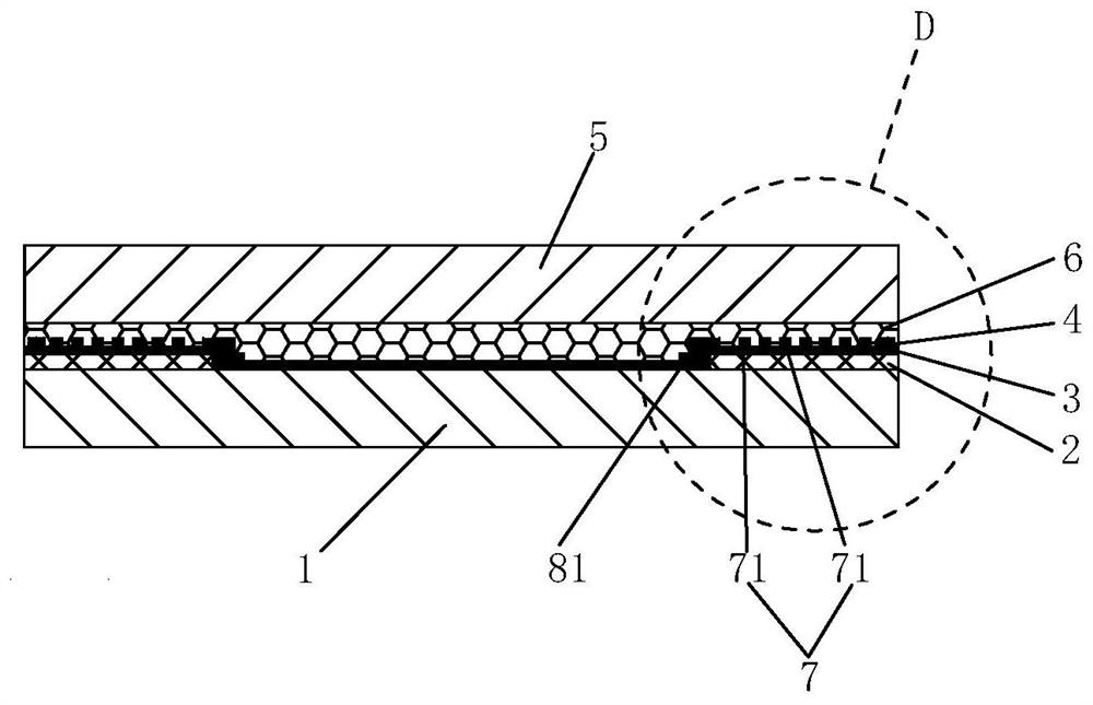
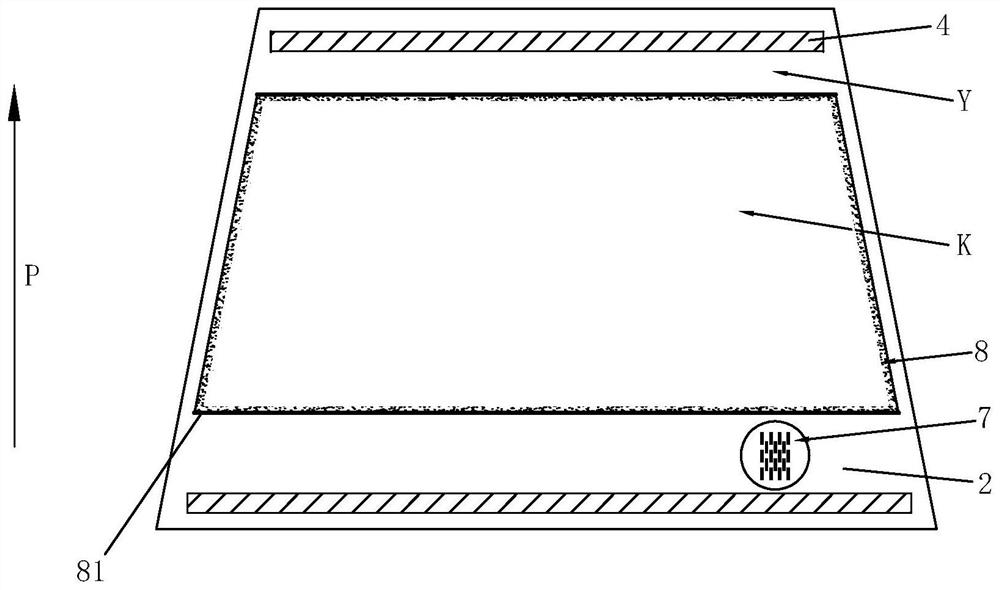
[0039] Please refer to figure 1 , figure 2 as well as Figure 7, the present embodiment provides a heatable laminated glass, comprising: an outer glass plate 1, an ink layer 2, a transparent conductive film 3, at least one pair of bus bars 4, an inner glass plate 5, a resin layer 6 and a conductive array 7, wherein : the ink layer 2 is ring-shaped and arranged on the inner surface of the outer glass plate 1 and is adjacent to or connected to the edge of the inner surface of the outer glass plate 1; the transparent conductive film 3 is arranged on the inner surface of the outer glass plate 1 and cover the ink layer 2; the resin layer 6 is arranged between the outer glass plate 1 and the inner glass plate 5; the conductive array 7 is arranged between a pair of the busbars 4 and the transparent conductive film on the ink layer 2 3 are in contact with each other, and the conductive array 7 includes a plurality of conductive elements 71 arranged in M rows and N columns, M and ...
Embodiment 2
[0066] The difference from Example 1 is:
[0067] Please refer to Figure 5 , viewed from the row direction R of the conductive array 7 , any one of the conductive elements 71 completely overlaps with another conductive element 71 in its adjacent column.
[0068] Specifically, because this embodiment solves the overheating problem of the transparent conductive film 3 layers on the ink layer 2 due to the increase in square resistance through the multiple conductive elements 71 arranged on the transparent conductive film 3 layers, and realizes the ability to The technical effect of uniform heating of the ink area Y.
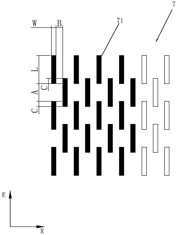
[0069] Please refer to Figure 5 , as a further optimization, in the conductive array 7, the current flow distance along the column direction E between any one of the conductive elements 71 and its adjacent another conductive element 71 is set to A, and along the row direction When the distance of R is set to B, the conductive array 7 satisfies: 2mm≤B≤30mm, 2mm≤...
Embodiment 3
[0072] The difference from Example 1 is:
[0073] Please refer to Image 6, as a further optimization, viewed from the row direction R and the column direction E of the conductive array 7, the adjacent row and adjacent column of any conductive element 71 are formed with vacancies that are not configured with other conductive elements 71, and more The conductive elements 71 are arranged at intervals across the vacancy.
[0074] Specifically, because this embodiment solves the overheating problem of the transparent conductive film 3 layers on the ink layer 2 due to the increase in square resistance through the multiple conductive elements 71 arranged on the transparent conductive film 3 layers, and realizes the ability to The technical effect of uniform heating of the ink area Y.
[0075] Please refer to Image 6 , as a further optimization, in the conductive array 7, the distance between any one of the conductive elements 71 and its adjacent vacancies along the column direct...
PUM
| Property | Measurement | Unit |
|---|---|---|
| Extension length | aaaaa | aaaaa |
Abstract
Description
Claims
Application Information
 - R&D Engineer
- R&D Manager
- IP Professional
- Industry Leading Data Capabilities
- Powerful AI technology
- Patent DNA Extraction
Browse by: Latest US Patents, China's latest patents, Technical Efficacy Thesaurus, Application Domain, Technology Topic.
© 2024 PatSnap. All rights reserved.Legal|Privacy policy|Modern Slavery Act Transparency Statement|Sitemap