Flat knitting machine automatic stop system and control method thereof

A control method and technology of flat knitting machines, which are applied in textiles, papermaking, knitting, etc., can solve problems such as shutdown alarm failure, insulation on the surface of the stop bar, and false alarms of overlapping foreign conductive objects, and achieve fast shutdown alarm response, sensitive monitoring, and Quick and accurate shutdown alarm response

Inactive Publication Date: 2021-02-12
苏州捷蓝智能设备有限公司
View PDF8 Cites 1 Cited by
  • Summary
  • Abstract
  • Description
  • Claims
  • Application Information

AI Technical Summary

Problems solved by technology

However, in order to avoid needle wear and yarn guide wear on the yarn during the weaving process of the flat knitting machine, the yarn will be oiled (coated with grease). When the yarn misses the loop, part of the grease on the yarn and The broken filaments will be scraped off and fly away, while the existing short-circuited bar is located under the yarn, and the flying grease and broken threads are attached to the bar, making the surface of the bar insulated or d

Method used


Image

  • Flat knitting machine automatic stop system and control method thereof
  • Flat knitting machine automatic stop system and control method thereof
  • Flat knitting machine automatic stop system and control method thereof

Examples


Embodiment 1

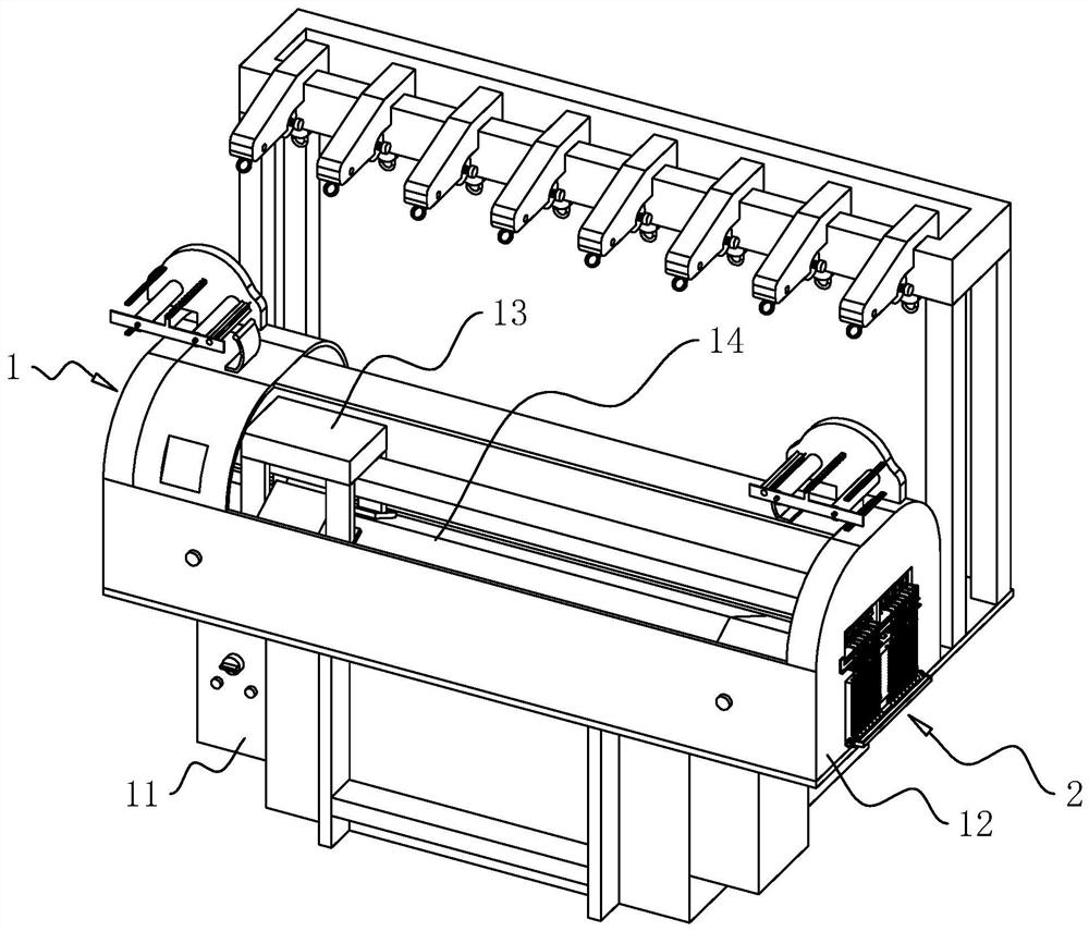
[0074] as attached figure 1 As shown, a flat knitting machine self-stop system includes a flat knitting machine 1 and an edge frame 2.

[0075] Wherein the flat knitting machine 1 comprises a base 11 at the bottom and a working room 12 installed above the base 11, and a yarn guide 13 and a needle plate 14 for weaving are installed in the working room 12. The yarn guide 13 slides on the needle plate 14 in the working chamber 12, pushes out the needle on the needle plate 14 and retreats, and knits the yarn.

[0076] as attached figure 2 As shown, the upper end of the side of the working chamber 12 is provided with a wire inlet 121 communicating with the inside and outside of the working chamber 12, so that the yarn can be passed into the working chamber 12. The size and shape of the thread inlet 121 can be determined according to actual design requirements, such as the number of yarns entering.

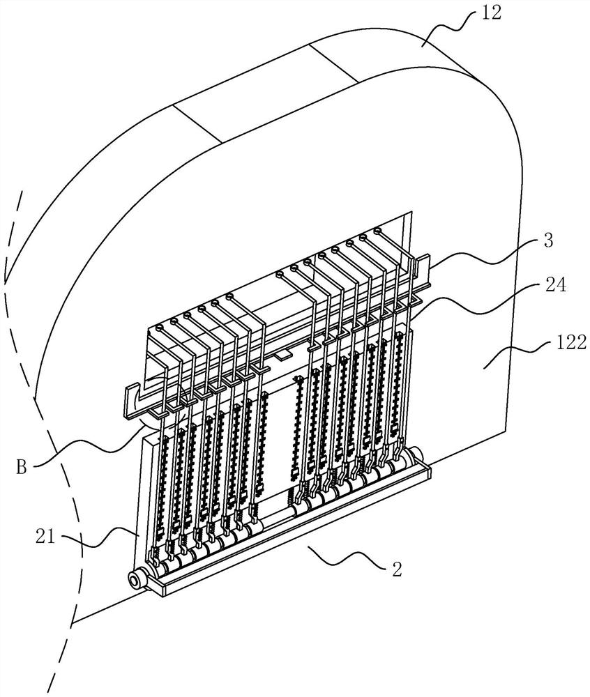
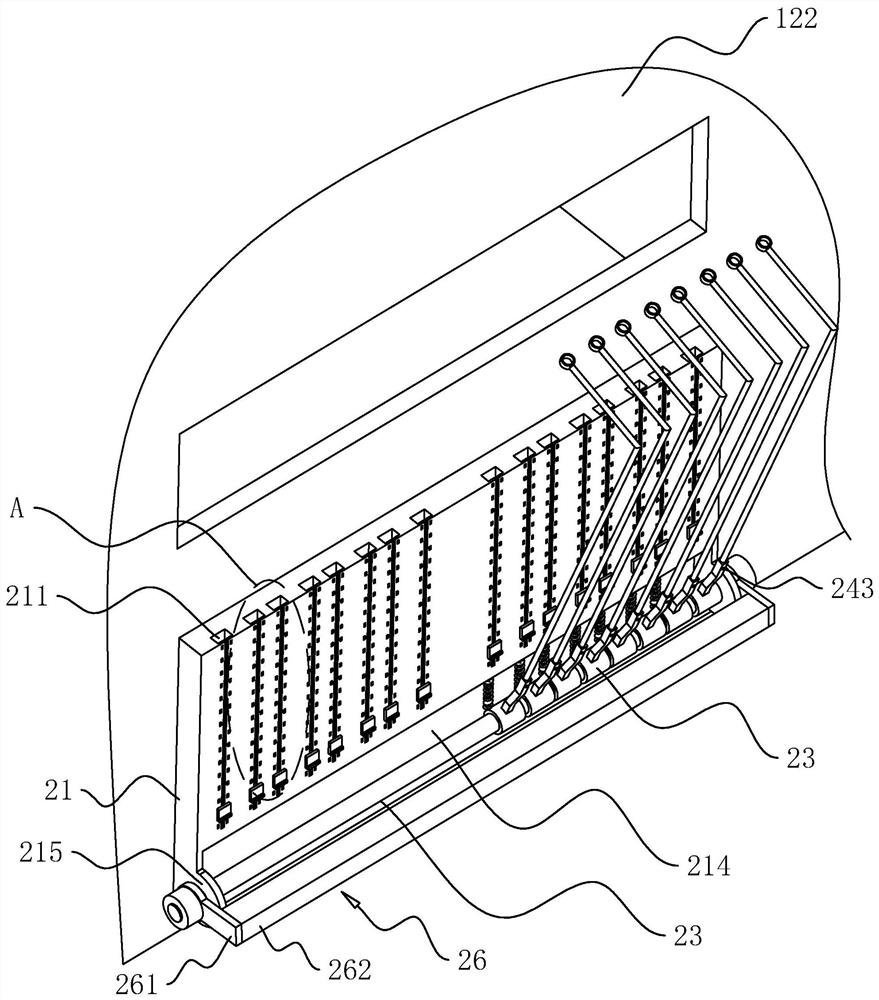
[0077] The edge frame 2 is fixed on the side of the working room 12 with the wi...

Embodiment 2

[0107] A flat knitting machine self-stop control method, based on the system of embodiment 1.

[0108] During work, yarn is worn in the wire loop 246 and the yarn supply direction is from the outside of the flat knitting machine 1 toward the interior of the flat knitting machine 1,

[0109] The upper end of the jumper 24 is only pulled by the yarn against the rotating shaft 23 except its own gravity, and it falls away from the frame body 21.

[0110] Its control steps are as follows:

[0111] S1: When the yarn is broken due to a work failure, the jumper 24 corresponding to the broken yarn loses yarn traction and turns toward the monitoring rod 262,

[0112] S2: The jumping rod 24 gradually approaches the monitoring rod 262, the magnetic sensor 2621 approaches the magnetic change threshold with the magnetic part 243, outputs a stop signal, and the flat knitting machine 1 stops.

[0113] For this control method, the magnetic field change induction is used to activate the shutd...

Embodiment 3

[0115] as attached Figure 10 As shown, a flat knitting machine self-stop system is further improved on the basis of Embodiment 1, and further includes a fault counting component 4 .

[0116] The fault counting assembly 4 includes counters 41 equal in number to jumpers 24 , and the counters 41 are installed on the installation side 122 and located below the fixing frame 3 . The distribution position of indicator 41 and the distribution position of jumper 24 are one by one. Indicator 41 is positioned at the top of rotating seat 241. Simultaneously, indicator 41 is electrically connected to magnetic sensor 2621 corresponding to the axial direction of vertical rotating shaft 23. Magnetic sensor 2621 outputs electric current every time. signal, the indicator 41 also receives the electrical signal, and makes the number on the indicator 41 increase by one.

[0117] The improvement effect of this embodiment:

[0118] Record the number of times that each jumper 24 breaks the line an...


PUM


Abstract

The invention relates to the field of textile machinery, and discloses a flat knitting machine automatic stop system which comprises a side thread frame. The side thread frame comprises a frame body,a monitoring assembly, a plurality of jumping rods and a rotating shaft, wherein one end of each jumping rod is connected to the outer side of the rotating shaft in a sleeving mode and is rotationallyconnected to the outer side of the rotating shaft, and a wire ring is fixed to the other end of each jumping rod. A magnetic piece is further fixed to the side face of each jumping rod, and the gravity center of each jumping rod deflects to the side, away from the frame body, of the rotating shaft. The monitoring assembly comprises a monitoring rod located on the side, away from the frame body, of the rotating shaft. The monitoring rod is provided with magnetic sensors equal to the jumping rods in number. When the jumping rods rotate away from the frame body with the rotating shaft as the axial direction, the magnetic pieces correspond to the magnetic sensors one to one and rotate to get close to the magnetic sensors. The magnetic sensors are directly or indirectly electrically connectedwith a working system of a flat knitting machine, electric connection is formed without contact, meanwhile, the requirement for limiting the impact force of the jump rods on the monitoring rod is alsomet, monitoring is sensitive, and shutdown alarm response is rapid and accurate. The invention discloses a control method of the flat knitting machine automatic stop system. The further improvement of the automatic stop system of the flat knitting machine is facilitated.

Description

technical field [0001] The present application relates to the field of textile machinery, in particular to a flat knitting machine self-stop system and a control method thereof. Background technique [0002] The computerized flat knitting machine is a double-needle plate latch weft knitting machine. Its cam device is like a set of plane cams. The stitches of the knitting needles can enter the grooves of the cams, move the cams, and force the knitting needles to move up and down regularly in the needle slots of the needle plate, and through the action of the needle hook and the needle latch. , the yarn can be woven into a knitted fabric. [0003] Existing flat knitting machines are equipped with a side frame for auxiliary yarn supply. The side frame is installed on the side of the flat knitting machine, and the yarn is folded at the side frame to enter the flat function. For example, the notification number is CN202705664U, a kind of side frame for flat knitting machines, w...

Claims


Application Information

Patent Timeline
IPC IPC(8): D04B35/16D04B35/18
CPCD04B35/16D04B35/18
Inventor 蔡杰王剑峰钱海东倪龙成黄建方
Owner 苏州捷蓝智能设备有限公司
Why Eureka
Try Eureka