
Coal mine hydraulic supporting column disassembling equipment

A coal mine hydraulic pressure and pillar technology, which is applied to mining equipment, pillars/brackets, earthwork drilling and mining, etc., can solve problems such as inability to lock, failure to disassemble, low working efficiency of the handle on the pillar, etc., and achieve good support and good Anti-slip effect, the effect of ensuring work efficiency

Inactive Publication Date: 2021-02-12
单佳莹
View PDF0 Cites 2 Cited by
  • Summary
  • Abstract
  • Description
  • Claims
  • Application Information

AI Technical Summary

Problems solved by technology

[0003] For the hydraulic column dismantling machine, when the column dismantling work is performed, one end of the column is usually stuck in the chuck at one end of the body, and the hydraulic drive is used to drive the block to fix it, and the other end of the column is supported by a support seat, which is set on On the guide rail of the body, there is no good fixing device for the support of the other end of the pillar in the prior art, and during the fixing process, the chuck drives the pillar to rotate, which may cause the pillar fixed in the support seat to rotate, which cannot be carried out very quickly. Good locking treatment leads to low work efficiency of the handle body on the dismantling pillar, and even causes disassembly failure, which affects the normal operation of the dismantling work. For this reason, the present invention proposes a coal mine hydraulic prop dismantling equipment to solve the above-mentioned problems. question

Method used


Image

  • Coal mine hydraulic supporting column disassembling equipment
  • Coal mine hydraulic supporting column disassembling equipment
  • Coal mine hydraulic supporting column disassembling equipment

Examples


Embodiment Construction

[0026] The technical solutions in the embodiments of the present invention will be clearly and completely described below. The embodiments of the present invention and all other embodiments obtained by persons of ordinary skill in the art without making creative efforts belong to the protection scope of the present invention.

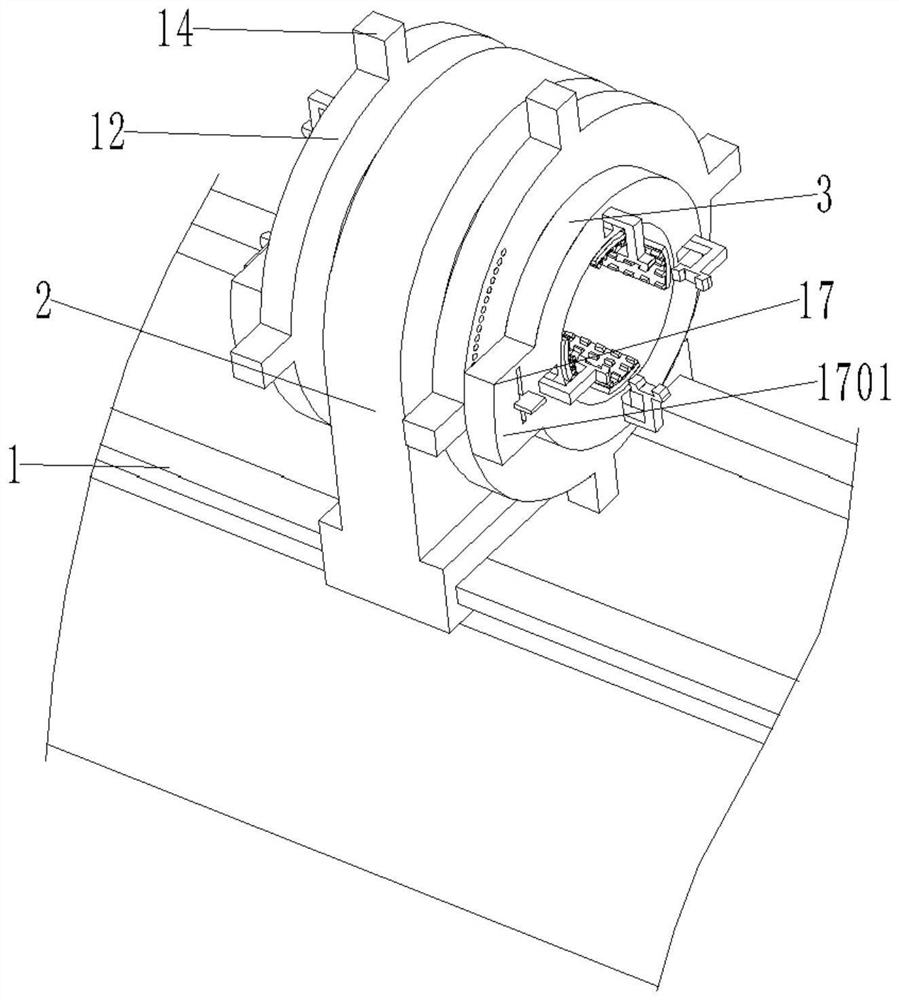
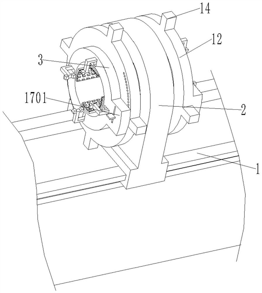
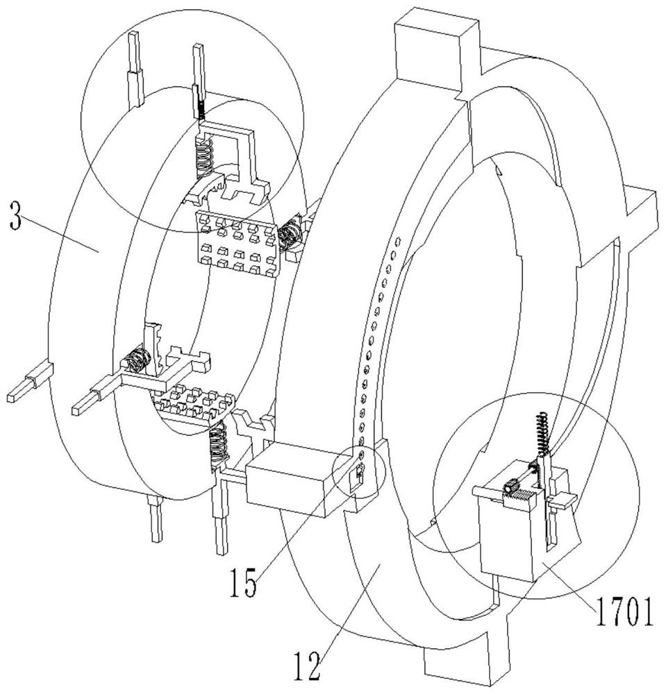
[0027] see figure see Figure 1 to Figure 8 , the present invention provides a technical solution: a coal mine hydraulic column dismantling equipment, the present invention includes a column dismantling machine guide rail 1, a support seat main body 2, a fixed convex ring 3, a movable collar 12 and a positioning locking mechanism 17;

[0028] A support seat main body 2 is provided on the guide rail 1 of the column dismantling machine, and a circular groove is provided through the support seat main body 2, and fixed convex rings 3 are arranged symmetrically on both sides of the support seat main body 2;

[0029] A first movable rod 4 is symmetrically ar...


PUM


Abstract

The invention discloses coal mine hydraulic supporting column disassembling equipment. The coal mine hydraulic supporting column disassembling equipment comprises a supporting column disassembling machine guide rail, a supporting seat main body, a fixed convex ring, a movable lantern ring and a positioning locking mechanism. According to the coal mine hydraulic supporting column disassembling equipment, when a supporting column disassembling machine is used for disassembling a supporting column, through the fixed convex ring and an arc-shaped clamping plate which are arranged on the two sidesof the supporting seat main body, a good supporting effect can be achieved on the supporting column, and the positioning and stabilizing effects can also be achieved on the supporting column; moreover, the good anti-skid effect can be achieved through the arranged extrusion strengthening block, a first anti-skid protruding block and a second anti-skid protruding block during clamping work, it is guaranteed that the position of the supporting column is firmly fixed during column disassembling work; and in addition, through the arranged positioning and locking mechanism, supporting and clampingof the supporting column are locked and fixed, stable operation of the column disassembling work is guaranteed nowadays, the working efficiency is guaranteed, and the column disassembling work is successfully conducted.

Description

technical field [0001] The invention relates to the technical field of decolumn machine equipment, in particular to a coal mine hydraulic prop decoupling equipment. Background technique [0002] Single hydraulic column dismantling machine is a special column dismantling equipment for single hydraulic prop. It can dismantle the severely corroded pillars that are difficult to disassemble with existing equipment, and basically realize the mechanization of the column dismantling process, speeding up the dismantling and maintenance process , is a better column dismantling equipment in China; it can complete the dismantling tasks of the three-purpose valve, base, handle body, top cover and live column, and realizes one machine with multiple functions; the main motor and the reducer are connected by a belt Transmission, strong overload capacity, low noise; the main shaft is equipped with an eccentric two-way self-tightening chuck (Type II machine), which has good rigidity, and the ...

Claims


Application Information

Patent Timeline
IPC IPC(8): E21D15/60
CPCE21D15/60
Inventor 单佳莹
Owner 单佳莹
Learn More