
compressor

A compressor and high-pressure technology, applied in the field of compressors, can solve the problems of increased exhaust loss and complicated exhaust process, so as to reduce exhaust loss, improve energy efficiency ratio, and solve the effect of increasing exhaust loss.

Active Publication Date: 2022-05-27
ZHUHAI GREE REFRIGERATION TECH CENT OF ENERGY SAVING & ENVIRONMENTAL PROTECTION
View PDF0 Cites 0 Cited by
  • Summary
  • Abstract
  • Description
  • Claims
  • Application Information

AI Technical Summary

Problems solved by technology

[0008] The main purpose of the present invention is to provide a compressor to solve the problem of increased exhaust loss due to the complicated exhaust process of the two-stage compressor on the low pressure cylinder in the prior art

Method used


Image

  • compressor
  • compressor
  • compressor

Examples


Embodiment Construction

[0031]It should be noted that the embodiments in the present application and the features of the embodiments may be combined with each other in the case of no conflict. The present invention will be described in detail below with reference to the accompanying drawings and in conjunction with the embodiments.

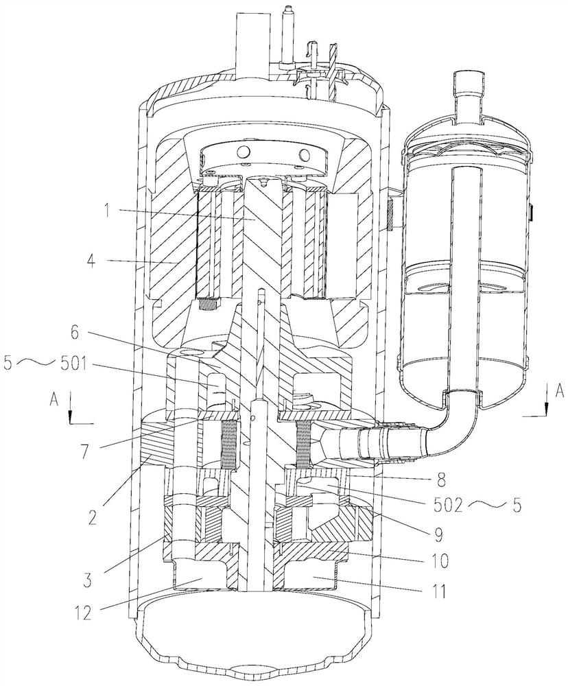
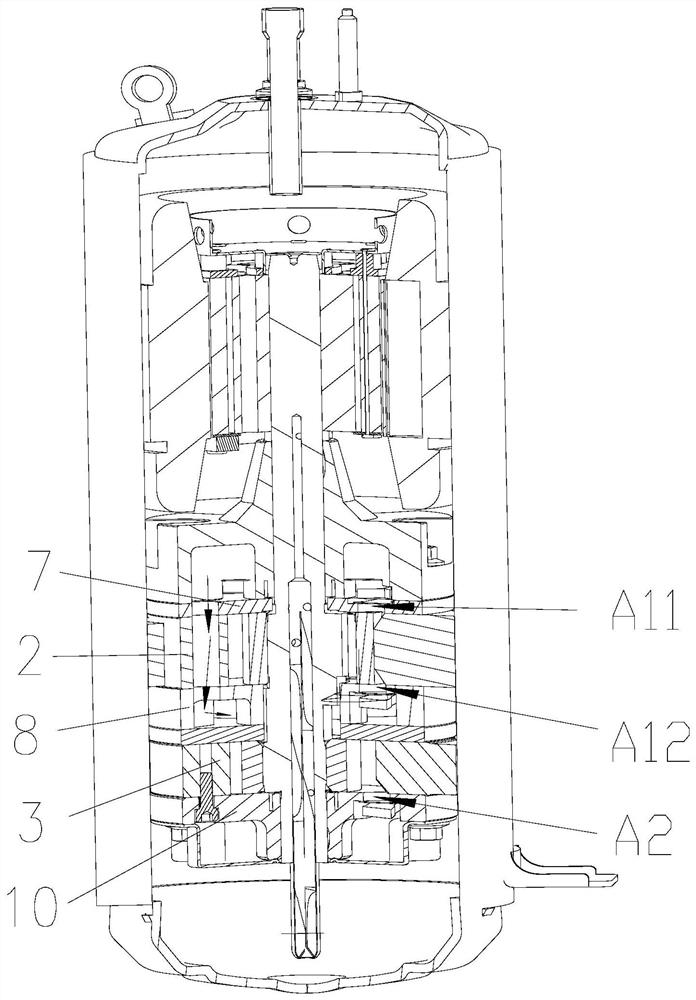
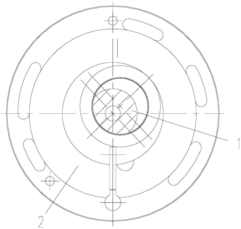
[0032] like Figure 1 to Figure 3 As shown, the present invention provides a compressor, including: a crankshaft 1; The side of the motor 4; the middle cavity 5, the middle cavity 5 is located on the side of the high pressure cylinder 3 close to the motor 4, and there is a medium pressure exhaust port between the low pressure cylinder 2 and the middle cavity 5, which is used to connect the low pressure cylinder 2 and the middle cavity. 5, so that the refrigerant flowing out of the low-pressure cylinder 2 flows into the high-pressure cylinder 3 after passing through the intermediate cavity 5; wherein, the low-pressure cylinder 2 exhausts the total gas flow area into the ...


PUM


Abstract

The invention provides a compressor, comprising: a crankshaft; a low-pressure cylinder and a high-pressure cylinder, the crankshaft is mounted on the low-pressure cylinder and the high-pressure cylinder, and the low-pressure cylinder is located on the side of the high-pressure cylinder close to the motor of the compressor; The side of the high-pressure cylinder close to the motor has a medium-pressure exhaust port between the low-pressure cylinder and the middle chamber, which is used to communicate with the low-pressure cylinder and the middle chamber, so that the refrigerant flowing out of the low-pressure cylinder flows into the high-pressure cylinder after passing through the middle chamber; among them, The total gas circulation area of ​​the low-pressure cylinder exhausting into the intermediate cavity through the medium-pressure exhaust port is S1, and the total displacement of the low-pressure cylinder exhausting into the intermediate cavity through the medium-pressure exhaust port is V1, 3.5×10 ‑3 ≤S1 / V1≤6.5×10 ‑3 . The compressor of the present invention solves the problem of increased exhaust loss due to the complicated exhaust process of the two-stage compressor placed above the low-pressure cylinder in the prior art.

Description

technical field [0001] The present invention relates to the field of compressors, in particular to a compressor. Background technique [0002] The rolling rotor type two-stage enthalpy increasing compressor has attracted more and more attention in the industry due to its simple structure, large operating pressure ratio and high reliability, and its application breadth and depth have been continuously expanded. The user proposed to develop a two-stage compressor with a larger displacement. [0003] The existing two-stage compressors in the industry have both a low-pressure cylinder and a high-pressure cylinder. In the vertical direction, the low-pressure cylinder is arranged below the high-pressure cylinder. The total displacement of the compressor is determined by the displacement of the low-pressure cylinder. Cylinder compressors also have two compression cylinders whose total displacement is the sum of the displacements of the two compression cylinders. When the compress...

Claims


Application Information

Patent Timeline
Patent Type & Authority Patents(China)
IPC IPC(8): F04C23/02F04C23/00F04C29/00F04C29/12
CPCF04C23/02F04C23/001F04C29/00F04C29/12
Inventor 魏会军胡艳军阙沛祯董辉
Owner ZHUHAI GREE REFRIGERATION TECH CENT OF ENERGY SAVING & ENVIRONMENTAL PROTECTION
Learn More