Transmission system for electric vehicle

A technology of transmission system and electric vehicle, applied in the field of transmission system, can solve the problems such as the lack of gears of the reducer and the inability to meet the requirements of the driver, and achieve the effect of reducing the weight of the whole vehicle, reducing the layout space requirements, and improving the power performance.

Active Publication Date: 2021-02-12
科大国创极星(芜湖)科技有限公司
View PDF15 Cites 1 Cited by
  • Summary
  • Abstract
  • Description
  • Claims
  • Application Information

AI Technical Summary

Problems solved by technology

[0002] Electric vehicles are usually equipped with a drive motor and a reducer, but because the reducer has fewer gears, it usually cannot meet the driver's requirements under various working conditions

Method used


Image

  • Transmission system for electric vehicle
  • Transmission system for electric vehicle

Examples


Embodiment Construction

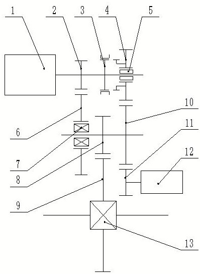
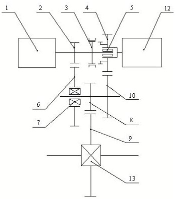
[0020] refer to figure 1 , the transmission system of the electric vehicle according to the first embodiment may include a first electric motor 1, an I gear pinion 2, a synchronizer 3, a II gear pinion 4, an I gear bull gear 6, a one-way clutch 7, a main reduction gear 8. The main reduction bull gear 9, the II gear bull gear 10, the auxiliary drive pinion 11 and the second motor 12.

[0021] The first electric motor 1 has a first output shaft, and the first output shaft is provided with an I gear pinion 2 , a synchronizer 3 and a II gear pinion 4 . The I gear pinion 2 and the synchronizer 3 can move synchronously with the first output shaft, and the II gear pinion 4 can move relatively with the first output shaft. For example, the II gear pinion 4 may be provided on the first output shaft through a rolling bearing 5 to move relative to the first output shaft.

[0022] The second motor 12 may be an induction motor, and the second motor 12 may have a second output shaft arrang...


PUM


Abstract

The invention relates to a transmission system of an electric vehicle. The transmission system comprises a first motor and a second motor, and comprises a two-gear speed reducer. According to the electric vehicle, a working condition range of the electric vehicle is expanded by arranging the second motor with low power.

Description

technical field [0001] The invention belongs to the field of vehicles, in particular to a transmission system for electric vehicles. Background technique [0002] Electric vehicles are usually equipped with a drive motor and a reducer, but because the reducer has fewer gears, it usually cannot meet the driver's requirements under various working conditions. Contents of the invention [0003] The object of the invention is to propose a drive train for an electric vehicle. [0004] Specifically, it is achieved through the following technical means: [0005] The transmission system for electric vehicles includes the first motor, I gear pinion, synchronizer, II gear pinion, I gear bull gear, one-way clutch, main reduction gear, main reducer bull gear, II gear bull gear, auxiliary Drive the pinion and the second motor, the first motor has a first output shaft, and the first output shaft is provided with an I gear pinion, a synchronizer and a II gear pinion, the I gear pinion ...

Claims


Application Information

Patent Timeline
Patent Type & Authority Applications(China)
IPC IPC(8): F16H3/12F16H57/023
CPCF16H3/12F16H3/126F16H57/023
Inventor 李解
Owner 科大国创极星(芜湖)科技有限公司
Why Eureka
Try Eureka