
Indoor harmful gas detection device with alarm function and use method

A harmful gas and detection device technology, applied in the direction of measuring devices, alarms, separation methods, etc., can solve the problems of device drop, increase user operations, and decrease the fixing effect, and achieve the effect of rapid detection

Pending Publication Date: 2021-02-12
孙霄
View PDF6 Cites 2 Cited by
  • Summary
  • Abstract
  • Description
  • Claims
  • Application Information

AI Technical Summary

Problems solved by technology

[0004] Existing gas detection devices that are easy to hang indoors are often hung with suction cups, but the fixing effect of the suction cups decreases after a long time, causing users to need to replace the suction cups. Since the suction cups are inconvenient to disassemble, this increases the user's operations and is not convenient. It is beneficial for the user to replace the suction cup. At the same time, the existing gas detection device that is easy to hang indoors will cause the device to fall due to the failure of the suction cup. This will easily damage the internal structure of the device, affect the normal operation of the device, and reduce the service life of the device. At the same time, the current Some gas detection devices lack the alarm function, and the alarm function of some devices is not perfect, so that the user cannot remotely know the dangerous situation, so that the gas spreads, which is likely to cause adverse effects and endanger the physical and mental health of others. Therefore, a An indoor harmful gas detection device with an alarm function and its application method

Method used


Image

  • Indoor harmful gas detection device with alarm function and use method
  • Indoor harmful gas detection device with alarm function and use method
  • Indoor harmful gas detection device with alarm function and use method

Examples


Embodiment

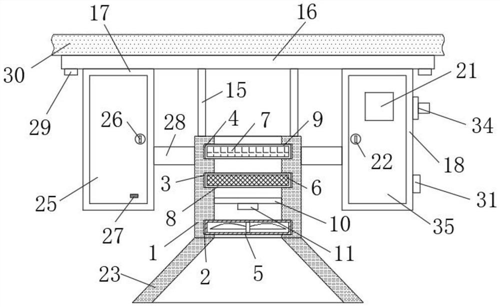
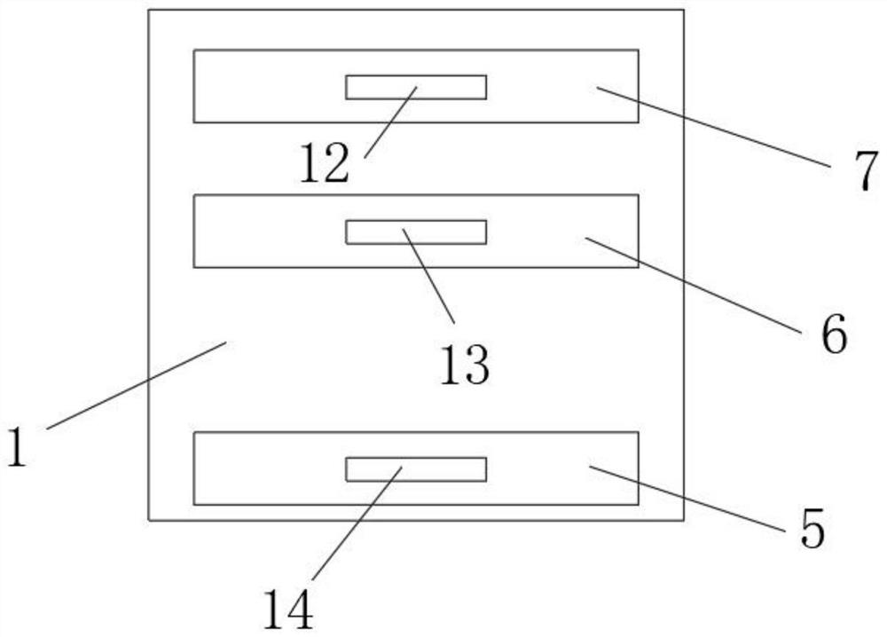
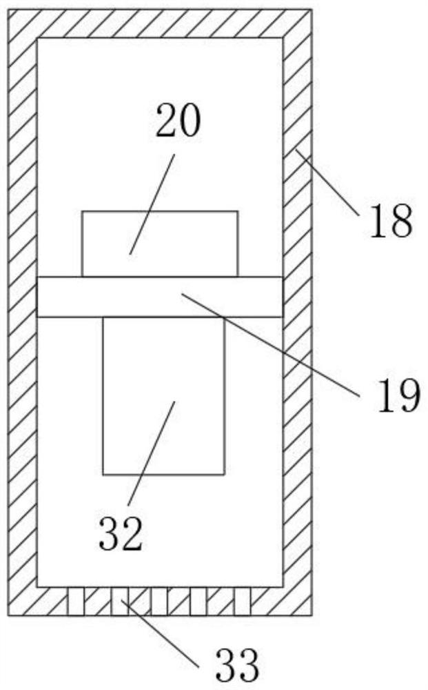
[0029] see Figure 1-7 , the present invention provides a technical solution: an indoor harmful gas detection device with an alarm function, including a first housing 1 and a wall top 30, and the inner side wall of the first housing 1 is respectively provided with a first chute 2, The second chute 3 and the third chute 4, the inner wall of the first housing 1 between the first chute 2 and the second chute 3 is fixedly connected with a support plate 10, and the bottom of the support plate 10 is equipped with a gas sensor device 11, the inside of the first chute 2 is slidably connected with an exhaust fan 5, the inside of the second chute 3 is slidably connected with a filter plate 6, the inside of the third chute 4 is slidably connected with an activated carbon plate 7, and the first shell The upper surface of the body 1 is symmetrically welded with four support rods 15, the top of the four support rods 15 is welded with a top plate 16, the bottom of the top plate 16 is respect...


PUM


Abstract

The invention provides an indoor harmful gas detection device with an alarm function and a use method. The device comprises a first shell and a wall top, and a first sliding groove, a second sliding groove and a third sliding groove are formed in the inner side wall of the first shell; a supporting plate is fixedly connected with the inner side wall, located between the first sliding groove and the second sliding groove, of the first shell, a gas sensor is installed at the bottom of the supporting plate, and an exhaust fan is slidably connected with the interior of the first sliding groove. The device is fixed to the lower portion of the wall top through expansion bolts, so that the device is more stable, the gas sensor is used for detecting indoor gas, floating harmful gas can be detectedmore quickly through cooperation of the gas sensor and the exhaust fan, a controller is used in cooperation with an alarm and an infrared emitter, an alarm can be given out while dangerous gas is detected, information is sent to mobile information equipment of a user, and the user is remotely reminded of information about emission of the harmful gas.

Description

technical field [0001] The invention relates to the technical field of harmful gas detection, in particular to an indoor harmful gas detection device with an alarm function and a use method. Background technique [0002] Gas refers to a deformable and flowable fluid without shape and volume. Gas is a state of matter. Gas is a fluid like liquid: it can flow and deform. Unlike liquid, gas can be compressed. If there is no limit ( In the case of container or force field), the gas can diffuse, its volume is not limited, the atoms or molecules of the gaseous substance can move freely with each other, the kinetic energy of the atoms or molecules of the gaseous substance is relatively high, and the gas can be divided into real gas and ideal gas , the gas form can be affected by its volume, temperature and its pressure. These elements constitute a number of gas laws, and the three can affect each other. [0003] Testing is a specified method to test the specified technical performa...

Claims


Application Information

Patent Timeline
Patent Type & Authority Applications(China)
IPC IPC(8): G01N33/00G08B21/12B01D53/04B01D39/00
CPCG01N33/0063G08B21/12B01D53/04B01D39/00
Inventor 孙霄尚超
Owner 孙霄
Learn More