Rail transit feed current measurement method based on shunt coefficient

A technology of shunt coefficient and feeding current, applied in the direction of measuring electricity, measuring device, only measuring current, etc., can solve the problem of not reducing the measurement points and so on.

Active Publication Date: 2021-02-12
STATE GRID HUBEI ELECTRIC POWER RES INST +2
View PDF9 Cites 0 Cited by
  • Summary
  • Abstract
  • Description
  • Claims
  • Application Information

AI Technical Summary

Problems solved by technology

The Chinese utility model patent "Converter station ground electrode feeder cable current test device" with application number 201520931635.3 proposes a converter station ground electrode feeder cable current test device, which includes a multi-channel wave recorder, test signal line, current mutual inductance There are no less than two channels on the multi-channel wave recorder, each channel is connected with a test signal line, and each test signal line is connected with a current transformer, the device will monitor all feed cable, does not reduce the measuring point
The Chinese invention patent "A Test Method for DC Shunt Coefficient of Grounding Grid of Converter Station" with the application number of 201410840717.7 discloses a test method for DC shunt coefficient of grounding grid of converter station. Inapplicable rail transit feeder cable shunt coefficient

Method used


Image

  • Rail transit feed current measurement method based on shunt coefficient
  • Rail transit feed current measurement method based on shunt coefficient
  • Rail transit feed current measurement method based on shunt coefficient

Examples


Embodiment Construction

[0025] The technical solutions in the present invention will be clearly and completely described below in conjunction with the accompanying drawings in the present invention.

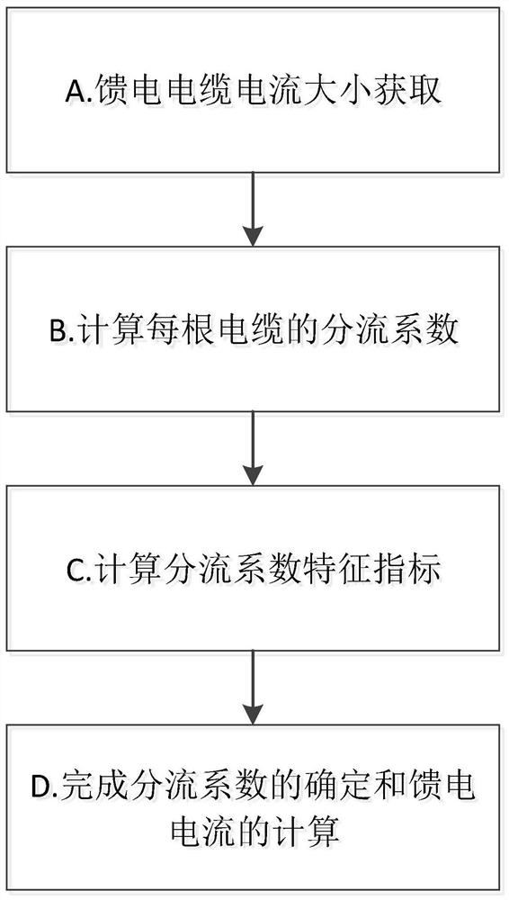
[0026] see figure 1 , is a schematic flow chart of one embodiment of a rail transit feeding current measurement method based on a shunt coefficient in the present invention, and the method includes the following steps:

[0027] A. To obtain the current of the feeder cable, measure the current of the rail transit feeder cable within a certain period through a clamp ammeter;

[0028] B. Based on the feeder cable current obtained in step A, calculate the shunt coefficient of each feeder cable in the measurement period, specifically:

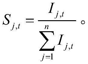
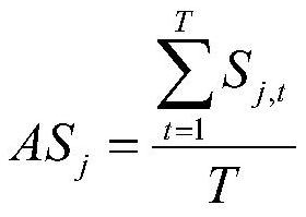
[0029] Assuming that the measurement period is T, the number of cables in the rail transit feeder loop is n, and the feed current of the jth feeder cable at time t is I j,t , where 1≤j≤n, 1≤t≤T, then the shunt coefficient of the jth feeder cable at time t is:

[0030]

...


PUM


Abstract

The invention provides a rail transit feed current measurement method based on a shunt coefficient. The method comprises the following steps: step A, acquiring the current of a feed cable, and measuring the current of a rail transit feed cable within a certain period through a clamp ammeter; step B, calculating a shunt coefficient of each feed cable in the measurement period based on the feed cable current obtained in the step A; step C, according to the feed cable shunt coefficient calculated in the step C, calculating characteristic indexes of the shunt coefficient, including an average value and a variance of the shunt coefficient; and step D, determining the shunt coefficient and calculating the feed current according to the shunt coefficient characteristic index calculated in the stepC. According to the method for determining the shunt coefficient of the feed cable, measurement points can be reduced, and the accuracy of rail transit feed current measurement is improved.

Description

technical field [0001] The invention relates to the technical field of rail transit feeder cables, in particular to a method for measuring rail transit feed current based on a shunt coefficient. Background technique [0002] The traction power supply of rail transit is DC current, and the DC current of traction is relatively large, which can reach thousands of amperes. The feeder circuit of rail transit is usually composed of multiple cables connected in parallel. When carrying out real-time online monitoring of rail transit feed current, if sensors are installed on each cable, on the one hand, it will increase investment, and on the other hand, it will increase the difficulty and workload of construction. In addition, due to the narrow space where rail transit feeder cables are laid, it is not conducive to the installation of sensors. [0003] Regarding the shunt coefficient of the feeder cable, DL / T 253-2012 proposed a related measurement method and data processing method...

Claims


Application Information

Patent Timeline
Patent Type & Authority Applications(China)
IPC IPC(8): G01R19/00G01R31/08
CPCG01R19/0092G01R31/088Y02E60/60
Inventor 唐泽洋阮羚沈煜姚勇邱凌李小双杨帆杨志淳胡伟雷杨宿磊王文烁蒋伟严方彬车方毅胡成奕
Owner STATE GRID HUBEI ELECTRIC POWER RES INST
Why Eureka
Try Eureka