Flanging face design method, flanging machining die and method and part
A design method and mold processing technology, which is applied in the field of stamping, can solve the problems of uneven exposed rounded corners of fenders, uneven outer gaps, and wavy flanges, and achieve the elimination of side wall wavy defects, high dimensional accuracy, The effect of improving quality
- Summary
- Abstract
- Description
- Claims
- Application Information
AI Technical Summary
Problems solved by technology
Method used
Image
Examples
Embodiment 1
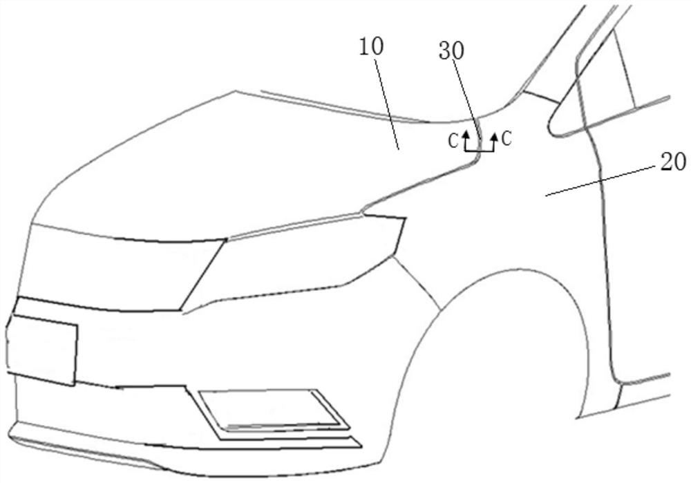
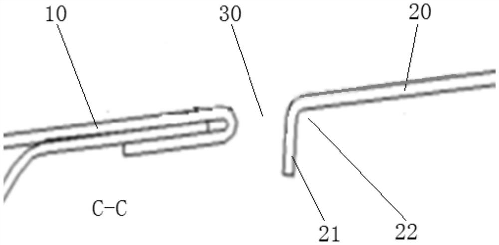
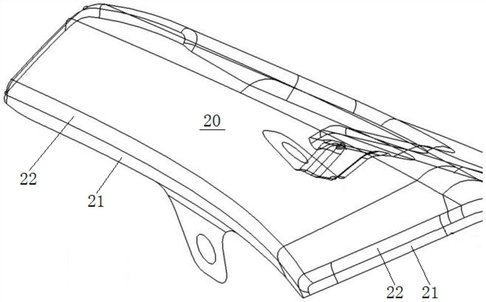
[0050] An embodiment of the present invention provides a method for designing a flanging surface. The overall design theory is as follows: first design the technical surface, and then correct the technical surface to obtain the theoretical flanged surface. The flanging surface design method is suitable for the flanging design of thin-plate automobile outer panels, which can ensure the consistency of the flanging gap of the mold, and effectively avoid the appearance of uneven rounded corners and wavy side walls caused by uneven flanging gaps. problems, and at the same time, it can effectively control the springback of parts, so that the parts after springback tend to be consistent with the theoretical state.
[0051] see Figure 8 , the flanging surface design method of the present embodiment comprises the following steps:
[0052] 1. Design process:
[0053] Design a flanging vector direction line 1, obtain the process surface based on the set flanging line and flanging vect...
Embodiment 2
[0060] Based on the same inventive concept, this embodiment provides a flanging processing mold, which is used to process the flanging surface designed by the flanging surface design method in the first embodiment above. Specifically, see Figure 10 The flanging processing mold 40 includes a punch 41 and a flanging insert 42, the punch 41 and the flanging insert 42 have a profile that cooperates with each other, and the profile includes rounded corners and the process surface 45 determined in the above-mentioned embodiment 1, When the process surface is projected with the direction of the flanging vector as the projection direction, the same line type as the flanging line 50 can be obtained, such as Figure 9 As shown; at least one of the punch 41 and the flanging insert 42 can move along the flanging vector direction line, so that the edge of the part motherboard is pressed down between the two profiles.
[0061] In the present embodiment, the punch 41 is a fixed part, which...
Embodiment 3
[0064] Based on the same inventive concept, this embodiment provides a flanging processing method, using the flanging processing mold 40 of the above-mentioned embodiment 2 to perform flanging processing on the part mother plate 20 .
[0065] see Figure 10 , the flanging processing method comprises the steps:
[0066] Place the parts motherboard 20 to be flanged on the punch 41, the edge of the parts motherboard 20 protrudes outside the punch 41, and the edge is used to form the flanging after being pressed;
[0067] Control the flanging insert 42 along the flanging vector direction line ( Figure 10 (indicated by the middle arrow) moves downward, and the edge is pressed between the two profiles, that is, in the flanging gap 44, and the edge bends around the profile of the punch 41 to form a process sheet with a process surface. Body cross-section as Figure 8 Middle flanging vector direction line 1;
[0068] Control the flanging insert 42 to pull upwards along the flangi...
PUM
| Property | Measurement | Unit |
|---|---|---|
| thickness | aaaaa | aaaaa |
| thickness | aaaaa | aaaaa |
| thickness | aaaaa | aaaaa |
Abstract
Description
Claims
Application Information
 - R&D
- Intellectual Property
- Life Sciences
- Materials
- Tech Scout
- Unparalleled Data Quality
- Higher Quality Content
- 60% Fewer Hallucinations
Browse by: Latest US Patents, China's latest patents, Technical Efficacy Thesaurus, Application Domain, Technology Topic, Popular Technical Reports.
© 2025 PatSnap. All rights reserved.Legal|Privacy policy|Modern Slavery Act Transparency Statement|Sitemap|About US| Contact US: help@patsnap.com


