New energy automobile hub grinding device

A new energy vehicle, wheel hub technology, applied in the direction of grinding drive device, grinding machine, grinding workpiece support, etc., can solve the problems of poor grinding flexibility, low grinding efficiency, affecting the overall appearance of the product, etc., to achieve flexible use and good grinding effect. Effect

Pending Publication Date: 2021-02-19
东营瑞尔泰机电科技有限公司
View PDF6 Cites 4 Cited by
  • Summary
  • Abstract
  • Description
  • Claims
  • Application Information

AI Technical Summary

Problems solved by technology

[0003] However, when the existing grinding device is grinding the wheel hub, the position adjustment of the grinding roller is not flexible enough, resulting in slow grinding speed, low grinding efficiency, and poor grinding flexibility, which not only affects the accuracy and pass rate of the product, but also affects the overall appearance of the product, resulting in polishing. Quality defects or inconsistent surface effects

Method used


Image

  • New energy automobile hub grinding device
  • New energy automobile hub grinding device
  • New energy automobile hub grinding device

Examples


Embodiment 1

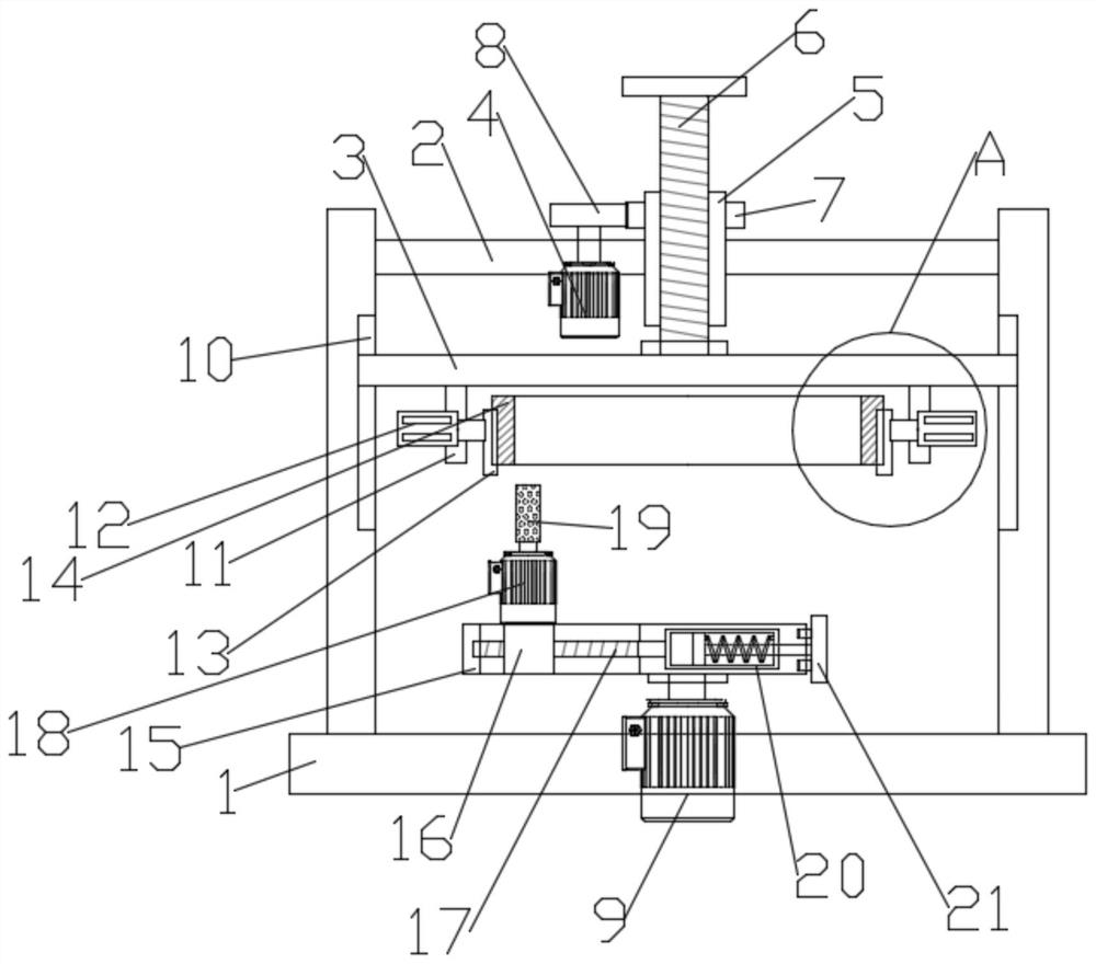
[0030] Such as figure 1 As shown, in the embodiment provided by the present invention, a new energy vehicle wheel hub grinding device includes a base 1, a bracket 2 is fixedly arranged on the base 1, and a bracket 2 for adjusting the lifting plate 3 is arranged on the top of the bracket 2. The lifting assembly at the height of the center; the inner walls of both sides of the support 2 are provided with guide rail grooves 10, and the end of the lifting plate 3 supports and slides in the guide rail grooves 10.

[0031] Further, in the embodiment of the present invention, the lower surface of the lifting plate 3 is provided with a clamping mechanism for clamping and fixing the hub 14; specifically, the clamping mechanism includes a The support plates 11 on the lower surfaces of both sides, the electric telescopic rod 12 is fixedly installed on the support plate 11, and the clamping mechanism also includes a clamp block 13, and the clamp block 13 is fixedly installed on the telesc...

Embodiment 2

[0039] Such as figure 1 As shown, in the embodiment provided by the present invention, a new energy vehicle wheel hub grinding device includes a base 1, a bracket 2 is fixedly arranged on the base 1, and a bracket 2 for adjusting the lifting plate 3 is arranged on the top of the bracket 2. The lifting assembly at the height of the center; the inner walls of both sides of the support 2 are provided with guide rail grooves 10, and the end of the lifting plate 3 supports and slides in the guide rail grooves 10.

[0040] Further, in the embodiment of the present invention, the lower surface of the lifting plate 3 is provided with a clamping mechanism for clamping and fixing the hub 14; specifically, the clamping mechanism includes a The support plates 11 on the lower surfaces of both sides, the electric telescopic rod 12 is fixedly installed on the support plate 11, and the clamping mechanism also includes a clamp block 13, and the clamp block 13 is fixedly installed on the telesc...


PUM


Abstract

The embodiment of the invention relates to the technical field of automobile hub machining, and particularly discloses a new energy automobile hub grinding device. The device comprises a base; a support is fixedly arranged on the base, and a lifting assembly used for adjusting the height of a lifting plate is arranged at the top of the support; a clamping mechanism used for clamping and fixing a hub is arranged on the lower surface of the lifting plate; and the base is further provided with a grinding mechanism used for machining clamping blocks. According to the embodiment, by means of the telescopic function of an electric telescopic rod, the clamping blocks can be pushed to move to clamp and fix the hub, then an adjusting screw rod is driven by an operation assembly to rotate, and the position of an adjusting screw sleeve is adjusted, so that the horizontal position of a grinding roller can be adjusted according to the inner diameter of the hub; a rotating base is driven to rotate by means of an adjusting motor, and the grinding roller is driven to rotate by means of a grinding motor so that the hub can be ground; and the advantages that the use is flexible, and the grinding effect is good are achieved.

Description

technical field [0001] The embodiment of the present invention relates to the technical field of automobile hub processing, in particular to a new energy automobile hub grinding device. Background technique [0002] The energy sources of new energy vehicles and traditional fuel vehicles are different, so the difference is mainly reflected in the power, but there is no obvious difference in the overall vehicle structure, so the basic process in the manufacture of new energy vehicles and fuel vehicles is roughly the same. Car manufacturing generally includes stamping, welding, grinding, painting and final assembly. When the wheel hub is manufactured, in order to ensure the accuracy and surface finish of the wheel hub, it is usually necessary to grind the wheel hub. [0003] However, when the existing grinding device is grinding the wheel hub, the position adjustment of the grinding roller is not flexible enough, resulting in slow grinding speed, low grinding efficiency, and po...

Claims


Application Information

Patent Timeline
Patent Type & Authority Applications(China)
IPC IPC(8): B24B5/44B24B5/35B24B41/06B24B47/12
CPCB24B5/44B24B5/35B24B41/06B24B47/12
Inventor 曹剑杨粤刘惠晴
Owner 东营瑞尔泰机电科技有限公司
Why Eureka
Try Eureka