A wood block cutting machine for building materials
A technology for wood blocks and building materials, applied in the field of wood block cutter changing machines for building materials, can solve the problems of inability to realize automatic and orderly transmission and changing cutters, and achieve the effects of reducing accidental injuries and improving accuracy
- Summary
- Abstract
- Description
- Claims
- Application Information
AI Technical Summary
Problems solved by technology
Method used
Image
Examples
Embodiment 1
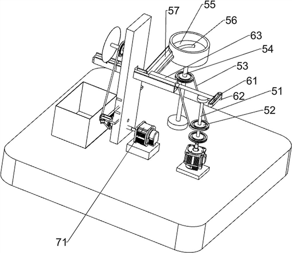
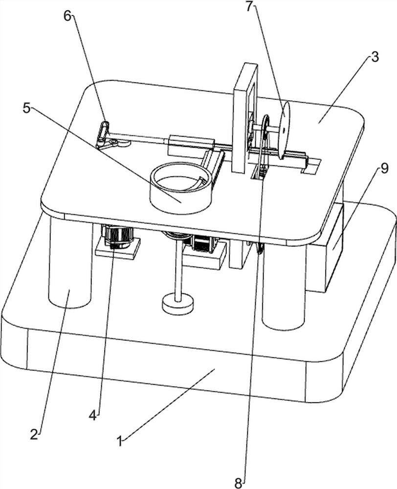
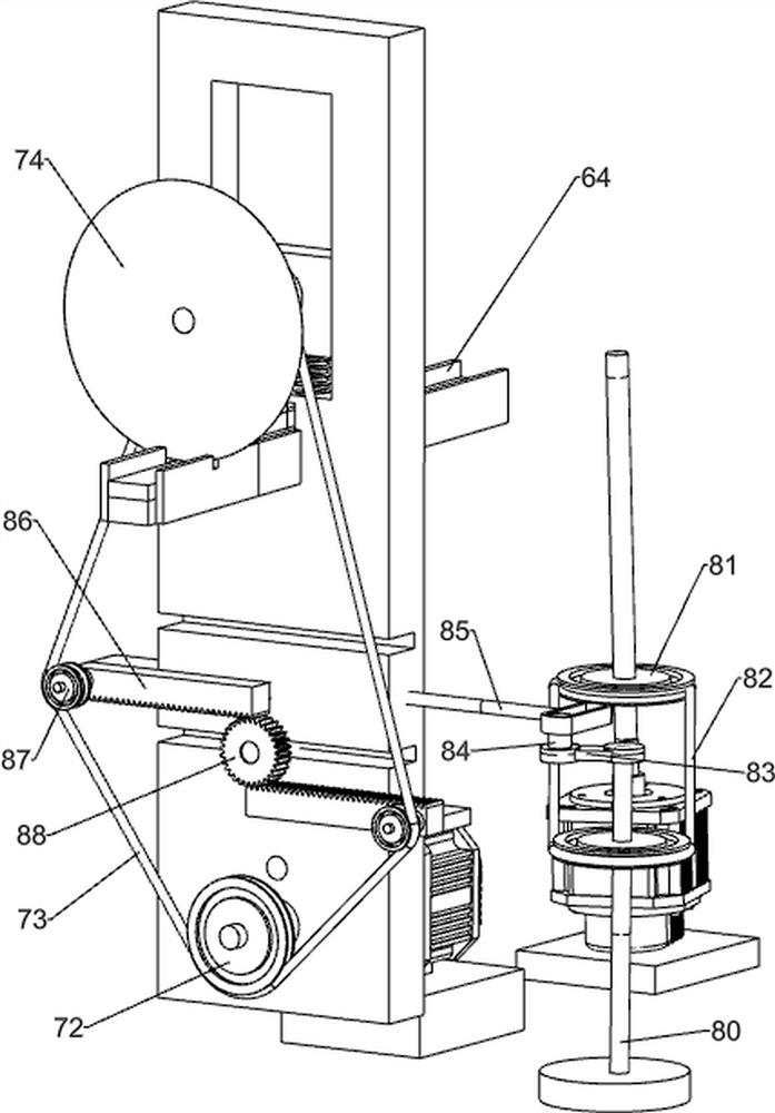
[0025] A wood block changing machine for building materials, such as figure 1 , figure 2 , image 3 , Figure 4 As shown, it includes a bottom plate 1, a bracket 2, a desktop 3, a first motor 4, a feeding mechanism 5, a pushing mechanism 6, a cutting mechanism 7 and a lifting mechanism 8. The bottom plate 1 is evenly provided with a bracket 2, and the top of the bracket 2 is provided with Desktop 3, a feeding mechanism 5 is provided on the front side of the top of the desktop 3, a first motor 4 is installed on the left side of the bottom plate 1, a pushing mechanism 6 is provided on the left side of the top of the desktop 3, and a cutting mechanism 7 is provided on the right side of the top of the desktop 3. 3. There is a lifting mechanism 8 on the right side of the top, and the lifting mechanism 8 is located on the left side of the cutting mechanism 7.
[0026] When people need to cut the wood block and change the knife, it is impossible to automatically cut and change th...
Embodiment 2
[0028] On the basis of Example 1, as figure 1 , figure 2 , image 3 , Figure 4 As shown, the unloading mechanism 5 includes a first rotating shaft 51, a first pulley 52, a first transmission belt 53, a second rotating shaft 54, an unloading table 55, a guide rod 56 and a first slideway 57. The output shaft is provided with a first rotary shaft 51, the upper side of the first rotary shaft 51 is provided with a first pulley 52, the front side of the bottom plate 1 is rotatably provided with a second rotary shaft 54, and the second rotary shaft 54 is also provided with a first pulley 52, A first transmission belt 53 is wound between the two first pulleys 52 , a feeding table 55 is arranged on the top of the second rotating shaft 54 , a first slideway 57 is arranged on the feeding table 55 , and the feeding table 55 is connected to the first slideway. 57 is rotatably connected, and the first slideway 57 is provided with a guide rod 56 .
[0029] After the cutting mechani...
Embodiment 3
[0037] On the basis of Example 2, as figure 1 As shown, a collection box 9 is also included, and a collection box 9 is provided on the right side of the bottom plate 1 .
[0038] When the slicing 74 is finished cutting the wood blocks and changing the knife, under the operation of the pushing mechanism 6, the wood blocks will be pushed to the right, so that the wood blocks after the knife changing will fall into the collection box 9, saving the workers the need to The wood blocks that have been changed are collected, and at the same time, the wood blocks that have been cut are pushed down from the second chute 64, so as not to hinder subsequent work.
PUM
 Abstract
Description
Claims
Application Information
 - R&D
- Intellectual Property
- Life Sciences
- Materials
- Tech Scout
- Unparalleled Data Quality
- Higher Quality Content
- 60% Fewer Hallucinations
Browse by: Latest US Patents, China's latest patents, Technical Efficacy Thesaurus, Application Domain, Technology Topic, Popular Technical Reports.
© 2025 PatSnap. All rights reserved.Legal|Privacy policy|Modern Slavery Act Transparency Statement|Sitemap|About US| Contact US: help@patsnap.com


