Garbage compressor push head with self-decompression function
A garbage compressor and self-relieving technology, which is used in trash cans, garbage collection, household appliances, etc., can solve the problems of shortening the service life of the compressor pusher and driving cylinder, hidden dangers, etc., and improve the environment and personnel operation in the station. Environment, reduce failure rate, and the effect of low equipment cost
- Summary
- Abstract
- Description
- Claims
- Application Information
AI Technical Summary
Problems solved by technology
Method used
Image

Examples
Embodiment 1
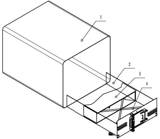
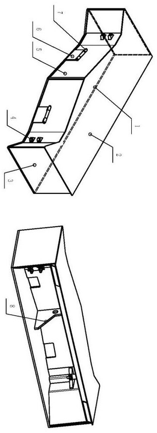
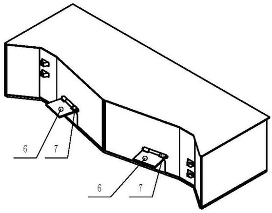
[0025] A push head 3 of a garbage compressor with a self-relieving function, characterized by comprising: a garbage collection box 1, a compression chamber 2, a compressor push head 3, a driving cylinder 4, a front plate assembly 5, and a pressure relief door 6 , a hinge and an internal support frame assembly 8, the compression push head is arranged inside the garbage collection box 1, the compression chamber 2 is located inside the compression push head, and the compression chamber 2 is provided inside for increasing the compression chamber 2 Strong internal bracket assembly, the front plate assembly 5 is set in front of the compression push head, the pressure relief door 6 is set on both sides of the front plate assembly 5, and the driving cylinder 4 is set in the garbage collection box 1 Inside, the front panel assembly 5 is provided with hinges, and the pressure relief door 6 is connected to the front panel assembly 5 through hinges.
Embodiment 2
[0027] A push head 3 of a garbage compressor with a self-relieving function, characterized by comprising: a garbage collection box 1, a compression chamber 2, a compressor push head 3, a driving cylinder 4, a front plate assembly 5, and a pressure relief door 6 , a hinge and an internal support frame assembly 8, the compression push head is arranged inside the garbage collection box 1, the compression chamber 2 is located inside the compression push head, and the compression chamber 2 is provided inside for increasing the compression chamber 2 Strong internal bracket assembly, the front plate assembly 5 is set in front of the compression push head, the pressure relief door 6 is set on both sides of the front plate assembly 5, and the driving cylinder 4 is set in the garbage collection box 1 Inside, the front panel assembly 5 is provided with hinges, and the pressure relief door 6 is connected to the front panel assembly 5 through hinges.
[0028] One side of the drive cylinder...
Embodiment 3
[0031] A push head 3 of a garbage compressor with a self-relieving function, characterized by comprising: a garbage collection box 1, a compression chamber 2, a compressor push head 3, a driving cylinder 4, a front plate assembly 5, and a pressure relief door 6 , a hinge and an internal support frame assembly 8, the compression push head is arranged inside the garbage collection box 1, the compression chamber 2 is located inside the compression push head, and the compression chamber 2 is provided inside for increasing the compression chamber 2 Strong internal bracket assembly, the front plate assembly 5 is set in front of the compression push head, the pressure relief door 6 is set on both sides of the front plate assembly 5, and the driving cylinder 4 is set in the garbage collection box 1 Inside, the front panel assembly 5 is provided with hinges, and the pressure relief door 6 is connected to the front panel assembly 5 through hinges.
[0032] The compression chamber 2 perf...
PUM
 Abstract
Description
Claims
Application Information
 - R&D
- Intellectual Property
- Life Sciences
- Materials
- Tech Scout
- Unparalleled Data Quality
- Higher Quality Content
- 60% Fewer Hallucinations
Browse by: Latest US Patents, China's latest patents, Technical Efficacy Thesaurus, Application Domain, Technology Topic, Popular Technical Reports.
© 2025 PatSnap. All rights reserved.Legal|Privacy policy|Modern Slavery Act Transparency Statement|Sitemap|About US| Contact US: help@patsnap.com