Steel-concrete composite continuous beam, connecting piece of hogging moment area of steel-concrete composite continuous beam and construction method

A technology of negative bending moment zone and connector, applied in the direction of bridge parts, bridges, building components, etc., can solve the problems of corrosion of low elastic modulus materials, weakening transverse shear resistance, affecting the crack resistance of concrete roofs, etc. Convenience and improved durability

Inactive Publication Date: 2021-02-19
SOUTHEAST UNIV
View PDF7 Cites 4 Cited by
  • Summary
  • Abstract
  • Description
  • Claims
  • Application Information

AI Technical Summary

Problems solved by technology

However, the prestress applied to the roof concrete in the negative moment area increases the shear stress at the junction of the concrete and the steel beam, and since the elastic modulus of the flat steel web is greater than the concrete elastic modulus, the prestress applied in the negative moment area is large Part of it is consumed on the steel web and steel flange, and the actual effective precompression stress applied to the roof concrete is very limited, which greatly affects the crack resistance of the concrete roof
[0003] At present, the commonly used anti-pull and non-sliding shear connectors realize that the connector does not transmit shear force by wrapping a layer of low elastic modulus material around the stud connector, but it weakens the longitudinal shear resistance of the connector and also weakens the Lateral shear resistance is reduced, and after long-term use, the low elastic modulus material around the stud connection may be corroded, forming voids around the connection, thereby affecting the durability of the structure

Method used


Image

  • Steel-concrete composite continuous beam, connecting piece of hogging moment area of steel-concrete composite continuous beam and construction method
  • Steel-concrete composite continuous beam, connecting piece of hogging moment area of steel-concrete composite continuous beam and construction method
  • Steel-concrete composite continuous beam, connecting piece of hogging moment area of steel-concrete composite continuous beam and construction method

Examples


Embodiment 1

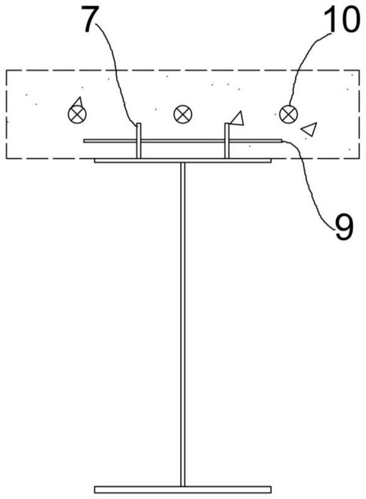
[0049] Such as figure 1 As shown, a connector suitable for the negative moment zone of steel-concrete composite continuous beams is disclosed. , including perforated plate 7, transverse reinforcement 9 and foam filling material 8; where:

[0050] The lower end surface of the perforated plate 7 can be welded and fixed to the top plate of the steel beam 4 in the negative moment zone, and the length extension direction of the perforated plate 7 is parallel to the direction along the bridge, and the perforated plate 7 is along its own The length extension direction is provided with a row of oval holes, the row of oval holes includes more than one oval hole, and the major axis direction of each oval hole is parallel to the length extension direction of the perforated plate 7;

[0051] The number of the transverse reinforcing bars 9 is consistent with the quantity of the oval holes; the length extension direction of each transverse reinforcing bar 9 is parallel to the transverse br...

Embodiment 2

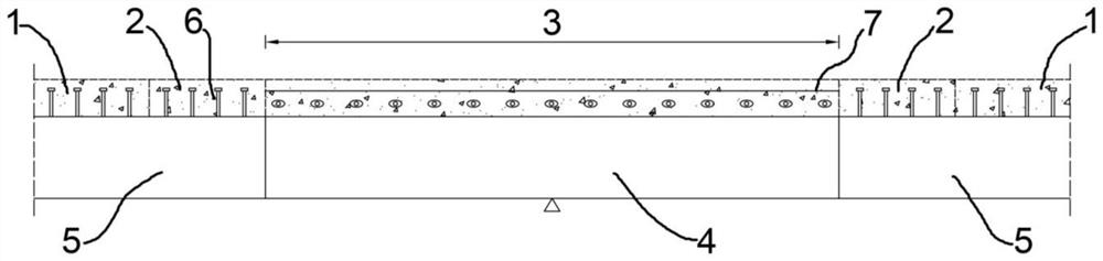
[0058] Such as Figure 1 to Figure 7 As shown, a steel-concrete composite continuous beam is disclosed, which includes the pull-out and non-shear open-hole plate connector described in Embodiment 1, specifically, the steel-concrete composite continuous beam includes steel beams, bolts Nail connectors 6, perforated plates 7, transverse steel bars 9, prestressed tendons 10 and concrete top slabs. The steel beams are divided into steel beams 4 in the negative bending moment area and steel beams 5 in the positive bending moment area. The steel girder 4 in the bending moment zone is located at both ends of the bridge along the direction of the bridge. The concrete roof is divided into the concrete roof 3 in the negative bending moment area, the concrete roof 1 in the positive bending moment area, and the reserved groove preset on the concrete roof 1 in the positive bending moment area, and the negative bending moment area is poured on the steel beam 4 roof in the negative bending ...

Embodiment 3

[0065] This embodiment provides a construction method for a steel-concrete continuous composite beam using the above-mentioned pullout-resistant and non-slip-resistant perforated plate connector, and the specific steps include:

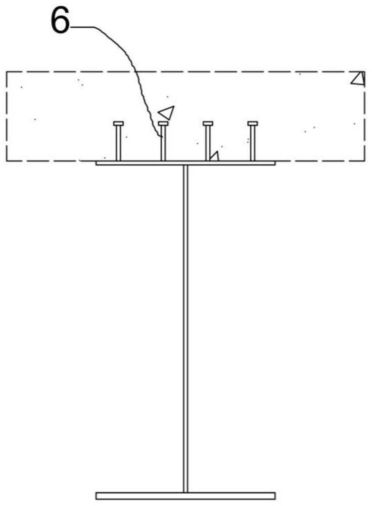
[0066] First, prefabricate the steel beam 5 in the positive moment zone and the steel beam 4 in the negative moment zone by selecting appropriate steel materials according to the environment, and weld the perforated plate 7 on the top plate of the steel beam 4 in the negative moment zone, and weld the steel beam 4 in the positive moment zone 5. Weld the stud connector 6 on the upper surface of the top plate.

[0067] Set up temporary buttresses at the construction site, erect steel beams 5 in the positive moment area and steel beams 4 in the negative moment area, and weld the joints of adjacent beams together.

[0068] After being closed, foam 8 is inserted into the opening of the perforated plate 7, and the transverse steel bar 9 is penetrated to for...


PUM


Abstract

The invention discloses a steel-concrete composite continuous beam, a connecting piece of a hogging moment area of the steel-concrete composite continuous beam and a construction method. The connecting piece comprises a perforated plate, transverse steel bars and a foam filling material; the perforated plate is fixedly welded to a top plate of a hogging moment area steel beam, the length extendingdirection of the perforated plate is parallel to the bridge direction of a bridge, a row of oval holes are formed in the perforated plate in the length extending direction of the perforated plate, and the long axis direction of each oval hole is parallel to the length extending direction of the perforated plate. The number of the transverse steel bars is consistent with that of the oval holes; the length extension direction of each transverse steel bar is parallel to the transverse bridge direction of the bridge, and the transverse steel bars penetrate through the oval holes in a one-to-one correspondence mode; and the foam filling material is a filling block body with a complete circular through hole in the middle. Therefore, the steel beam in the hogging moment area and the concrete topplate in the hogging moment area can longitudinally slide, the tensile stress of a bridge deck slab in the area is effectively reduced, meanwhile, the transverse anti-shearing effect and the verticalanti-pulling capacity are reserved, and the safety and durability of the bridge are improved.

Description

technical field [0001] The invention relates to a steel-concrete composite continuous beam and a connector and a construction method of the negative bending moment area thereof, belonging to the technical field of bridge structures. Background technique [0002] The steel-concrete composite structure simply supported beam takes advantage of the compression resistance of concrete, and replaces the concrete in the mid-span tension zone with a steel structure, effectively avoiding the cracking of the lower concrete. However, the main girder in the negative moment zone of the steel-concrete composite continuous girder bridge is in an unfavorable stress state where the steel girder is under compression and the concrete bridge deck is under tension. The bridge deck concrete bears a large tensile stress and is prone to cracking problems. Rainwater may seep around the shear connectors and cause the connectors to rust, resulting in a decrease in structural rigidity and durability. T...

Claims


Application Information

Patent Timeline
Patent Type & Authority Applications(China)
IPC IPC(8): E01D2/00E01D19/00E01D21/00E04C5/00E04C5/01
CPCE01D2/00E01D19/00E01D21/00E04C5/00E04C5/01
Inventor 吴文清戴金希石中琦王新雅刘泓佚
Owner SOUTHEAST UNIV
Why Eureka
Try Eureka