
Height vernier caliper and manufacturing process

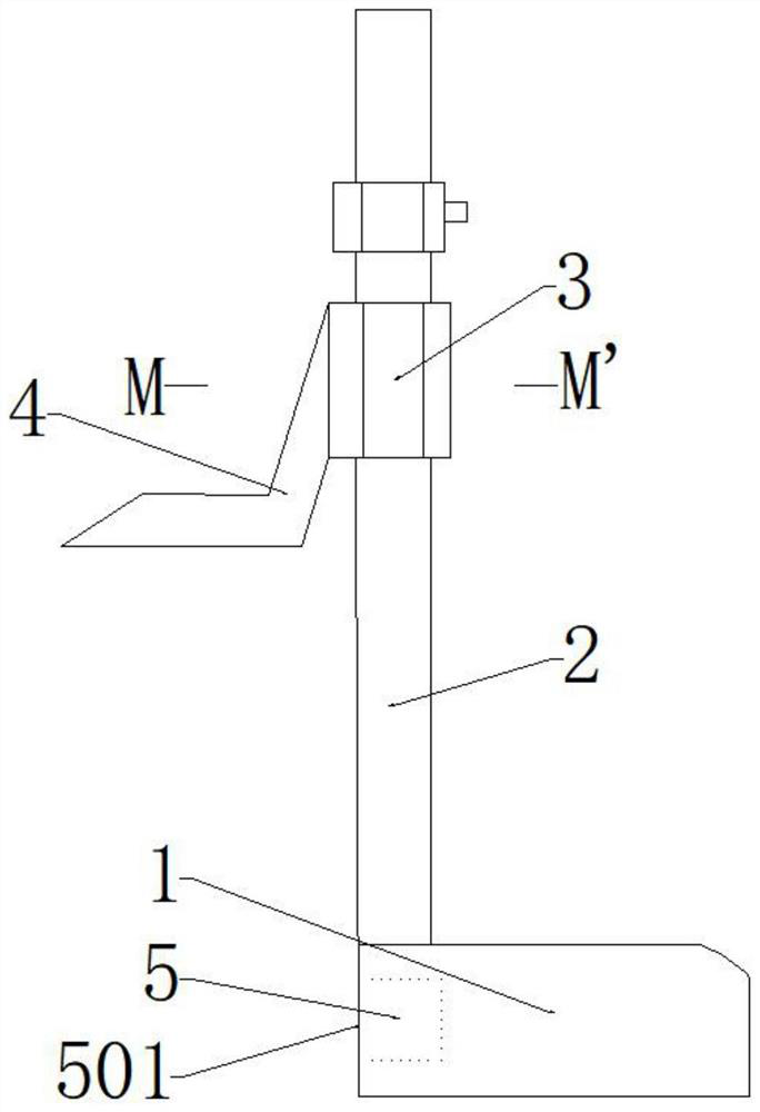
A vernier caliper and height technology, which is applied in the field of measuring rulers, can solve the problems of difficult transportation and storage, easy wear and tear of vernier and ruler rods, and large installation space, and achieves the effects of easy transportation and storage, light weight, and pollution avoidance.

Pending Publication Date: 2021-02-19
台州德量工具有限公司
View PDF0 Cites 0 Cited by
  • Summary
  • Abstract
  • Description
  • Claims
  • Application Information

AI Technical Summary

Problems solved by technology

[0004] 1. After long-term use, it is easy to wear between the vernier and the ruler rod. After wear, there will be a swing between the ruler rod and the vernier, which will cause errors during measurement and affect the measurement accuracy;
[0005] 2. The base of the traditional height vernier caliper is made of cast iron, the rod and the vernier are made of carbon steel, affected by the measurement environment, it may be corroded by various media during the measurement process;
[0006] 3. The ruler rod is fixed on the base. When not in use, due to the high ruler rod, the whole device will take up a lot of space and it is difficult to transport and store;
[0007] 4. In the traditional manufacturing process of height vernier calipers, the base needs to be treated with cast iron sanding, surface grinding, machining center and painting; the ruler bar needs to be customized with carbon steel profiles, sawing machine cutting, heat treatment, sandblasting treatment, and hard chrome plating; The cursor needs to be cut by wire cutting, machining center, heat treatment, surface grinding, sandblasting, hard chrome plating, among which, cast iron sanding, surface grinding, painting treatment, carbon steel profile customization, heat treatment, sandblasting, hard chrome plating, Production processes such as wire cutting and blanking will pollute the environment

Method used


Image

  • Height vernier caliper and manufacturing process
  • Height vernier caliper and manufacturing process

Examples


Embodiment Construction

[0036] In order to illustrate the present invention more clearly, the present invention will be further described below in conjunction with preferred embodiments. Those skilled in the art should understand that the content specifically described below is illustrative rather than restrictive, and should not limit the protection scope of the present invention.

[0037] In describing the present invention, it is to be understood that the terms "center", "upper", "lower", "front", "rear", "left", "right", "vertical", "horizontal", The orientations or positional relationships indicated by "top", "bottom", "inner", "outer", etc. are based on the orientations or positional relationships shown in the drawings, and are only for the convenience of describing the present invention and simplifying the description, rather than indicating or implying the It should not be construed as limiting the invention that a device or element must have a particular orientation, be constructed, and oper...


PUM


Abstract

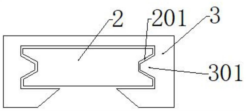
The invention discloses a height vernier caliper and a manufacturing process. The height vernier caliper comprises a base, a caliper rod, a vernier and a matching piece, wherein a mortise and tenon groove is formed in the base, a tenon matched with the mortise and tenon groove is arranged on the caliper rod, the tenon of the caliper rod is pressed into the mortise and tenon groove of the base andpenetrates through the mortise and tenon groove and the tenon through a pin on the matching piece, the caliper rod is arranged on the base in a vertically upward mode, the vernier is connected to thecaliper rod in a sliding mode, a scribing measuring jaw is fixed to one side of the vernier, at least two limiting parts are arranged at the connecting position of the vernier and the caliper rod, andrecesses matched with the limiting parts are formed in the surface of the caliper rod. The height vernier caliper is durable, simple in structure and easy to disassemble, and the use experience of auser is improved.

Description

technical field [0001] The invention relates to the technical field of measuring rulers, in particular to a height vernier caliper and a manufacturing process. Background technique [0002] The existing height vernier caliper includes a base, a ruler rod installed vertically upward on the base, a vernier installed on the ruler rod and a marking claw installed on the vernier, which is mainly used to measure the height of the workpiece, and is a precision tool itself. Measuring tool, when measuring the height of the workpiece, first move the vernier so that the marking jaws touch the workpiece, then tighten the fastening screw, adjust the micro-movement device so that the marking jaws clamp the workpiece, and then read the height value. [0003] However, there are many problems in the traditional height vernier caliper, such as: [0004] 1. After long-term use, it is easy to wear between the vernier and the ruler rod. After wear, there will be a swing between the ruler rod an...

Claims


Application Information

Patent Timeline
Patent Type & Authority Applications(China)
IPC IPC(8): G01B3/20G01B1/00
CPCG01B1/00G01B3/20
Inventor 陈德才
Owner 台州德量工具有限公司
Learn More