Circuit inspection robot system

A technology for inspecting robots and circuits, which is applied to circuit devices, instruments, electrical components, etc., and can solve the problems of low efficiency of human inspection

Inactive Publication Date: 2021-02-19
江苏赛愽智能制造研究院有限公司
View PDF7 Cites 0 Cited by
  • Summary
  • Abstract
  • Description
  • Claims
  • Application Information

AI Technical Summary

Problems solved by technology

[0005] The technical problem to be solved by the present invention is: to overcome the deficiencies of the prior art, to provide a robot system for circuit inspection, and to solve the problem of low efficiency of manual inspection of circuits in the past

Method used


Image

  • Circuit inspection robot system

Examples


Embodiment Construction

[0027] The present invention will be further described in conjunction with specific embodiment now. These drawings are simplified schematic diagrams only to illustrate the basic structure of the present invention in a schematic way, so they only show the components relevant to the present invention.

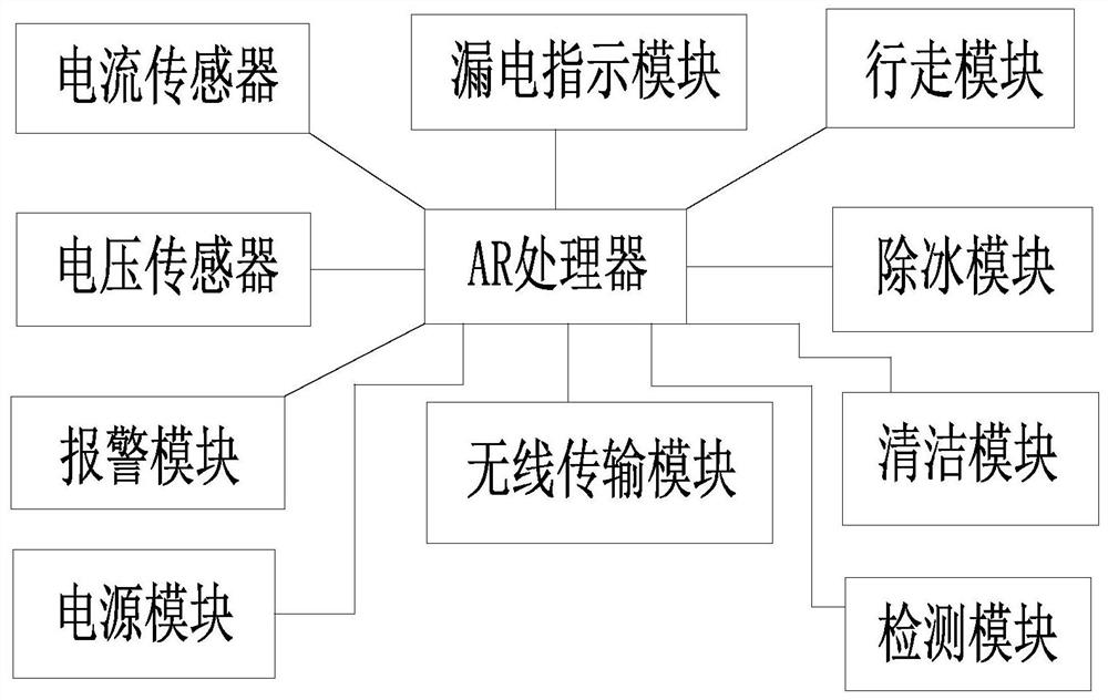
[0028] Such as figure 1 As shown, a circuit inspection robot system, including

[0029] Current sensor, leakage indication module, walking module, voltage sensor, AR processor, deicing module, alarm module, power supply module, wireless transmission module and cleaning module;

[0030] the current sensor is adapted to detect the current in the circuit;

[0031] The leakage indication module is suitable for light indication when the circuit is leakage;

[0032] The walking module is suitable for controlling the robot to walk on the wire;

[0033] the voltage sensor is adapted to detect voltage in the circuit;

[0034] the deicing module is adapted to remove ice from electrica...


PUM


Abstract

The invention relates to a circuit inspection robot system which comprises a current sensor, an electric leakage indication module, a walking module, a voltage sensor, an AR processor, a deicing module, an alarm module, a power module, a wireless transmission module and a cleaning module. The electric wire deicing robot can safely walk on the electric wire to detect the voltage and current of theelectric wire, and can deice and clean the electric wire, so that the electric wire can be inspected, cleaned and maintained.

Description

technical field [0001] The invention relates to the field of power grid detection, in particular to a circuit inspection robot system. Background technique [0002] In order to ensure the normal operation of the power system, the wires need to be inspected and maintained frequently, and the wires with serious defects need to be replaced and repaired in time. [0003] At present, the inspection of the conveyor line mainly relies on manual inspection. Manual inspection is risky, labor-intensive, and time-consuming, which affects the quality and efficiency of inspections. [0004] With the continuous increase of the scale of the power grid, if we still rely solely on human inspection, there is not so much human reserve. Therefore, it is necessary to develop robots to inspect the lines. Contents of the invention [0005] The technical problem to be solved by the present invention is: to overcome the deficiencies of the prior art, provide a circuit inspection robot system, and...

Claims


Application Information

Patent Timeline
Patent Type & Authority Applications(China)
IPC IPC(8): G01D21/02H02G1/02H02G7/00H02G7/16H02J50/10
CPCG01D21/02H02G1/02H02G7/00H02G7/16H02J50/10
Inventor 支海波
Owner 江苏赛愽智能制造研究院有限公司
Why Eureka
Try Eureka