
Air rudder thermal environment modeling method and device and storage medium

A modeling method, air rudder technology, applied in computer-aided design, design optimization/simulation, special data processing applications, etc. The effect of small prediction deviation, guaranteed grid amount, and improved simulation accuracy and calculation efficiency

Pending Publication Date: 2021-02-19
CHINA ACAD OF LAUNCH VEHICLE TECH
View PDF0 Cites 2 Cited by
  • Summary
  • Abstract
  • Description
  • Claims
  • Application Information

AI Technical Summary

Problems solved by technology

However, because the local shock boundary layer disturbs the flow is very complex and has strong multi-scale flow characteristics, there are high requirements for the quality of numerical simulation grid division
The results of traditional air rudder grid division lead to large deviations in the prediction of thermal environment, especially the simulation accuracy of heat flow in the interference area of ​​the aircraft surface and the interference area of ​​the rudder surface is low, and it is easy to cause excessive grid volume and cause simulation Computational efficiency drops

Method used


Image

  • Air rudder thermal environment modeling method and device and storage medium
  • Air rudder thermal environment modeling method and device and storage medium
  • Air rudder thermal environment modeling method and device and storage medium

Examples


Embodiment 1

[0029] This embodiment provides a grid modeling method for the thermal environment of the air rudder, which can be used to model the thermal environment of the air rudder in the aircraft, and improve the prediction deviation of the thermal environment.

[0030] In practical applications, the air rudder thermal environment grid modeling method can be implemented by computer programs, such as application software, etc.; or, the method can also be implemented as a medium that stores related computer programs, such as U disk, cloud disk, etc. or, the method can also be implemented by an entity device integrated or installed with a relevant computer program, such as a chip, a mobile smart device, and the like.

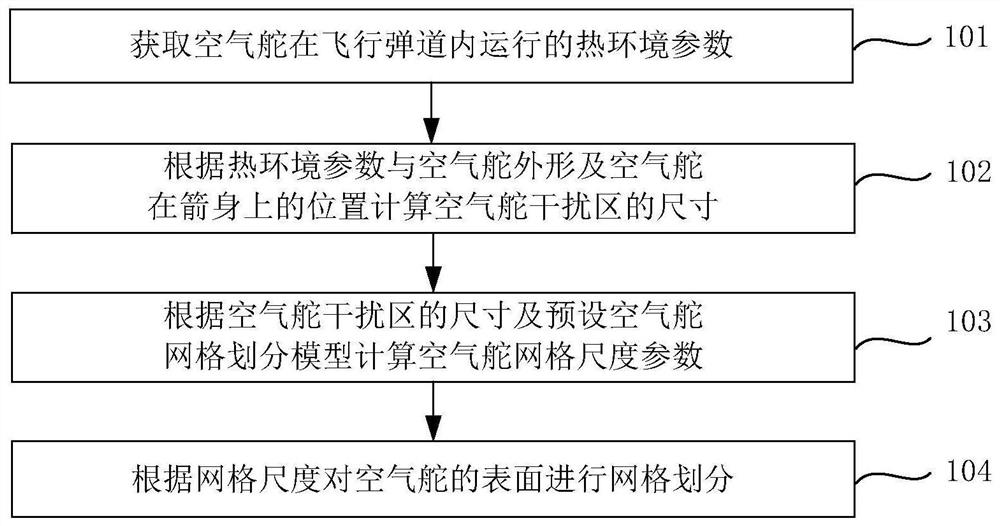
[0031] figure 1 It is a flow chart of the air rudder thermal environment modeling method provided in Embodiment 1 of the present application. Such as figure 1 As shown, the air rudder thermal environment modeling method provided in this embodiment includes:

[0032] Step...

Embodiment 2

[0042] This embodiment optimizes the air rudder thermal environment grid modeling method on the basis of the above embodiments.

[0043] The preset air rudder grid division model may be preset, or may be determined before step 102 .

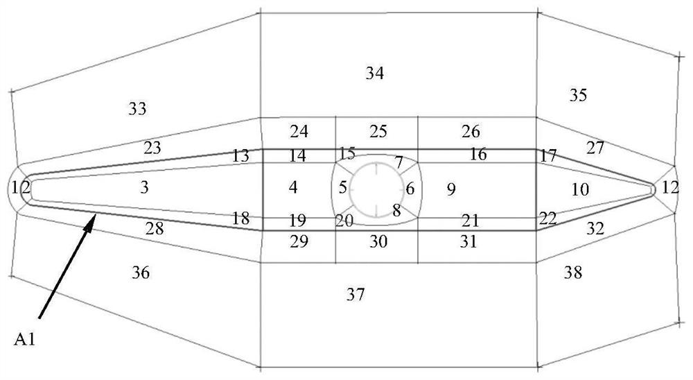
[0044] Specifically: before the above step 103 calculates the air rudder grid scale parameters according to the size of the air rudder interference area and the preset air rudder grid division model, it is also possible to determine the preset according to the air rudder shape and the position of the air rudder on the arrow body. Air rudder meshing model.

[0045] After the preset air rudder meshing model is determined, the preset air rudder meshing model can also be adjusted according to the size of the air rudder interference area, so that it has a higher degree of fit with the real operating environment of the air rudder.

[0046] A specific implementation of the above step 102: calculate the thickness of the boundary layer of incoming flow a...

Embodiment 3

[0051] This embodiment optimizes the grid modeling method for the thermal environment of the air rudder on the basis of the above embodiments, and in particular provides a specific implementation of the grid modeling method for the thermal environment of the air rudder.

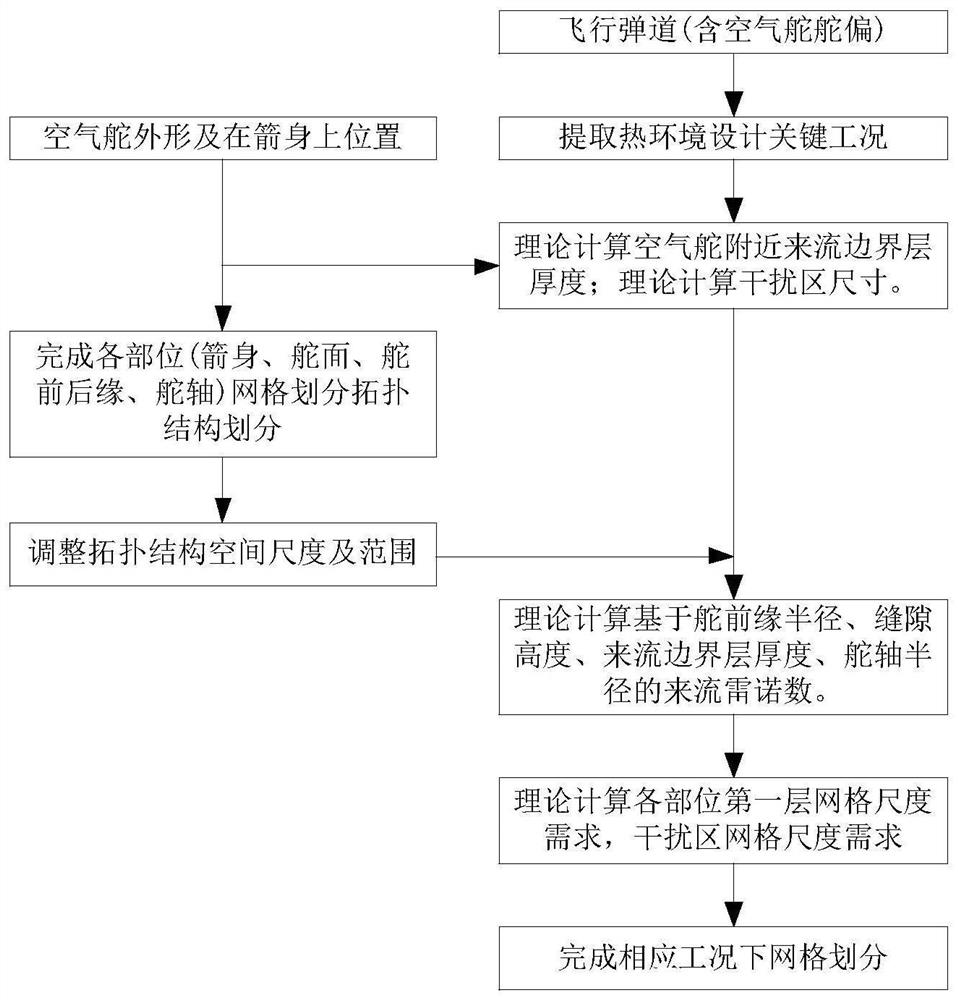
[0052] image 3 It is a flow chart of the air rudder thermal environment modeling method provided in the third embodiment of the present application. Such as image 3 As shown, the method provided in this embodiment includes the following steps:

[0053] The first step: extract the key working condition parameters of flight trajectory thermal environment design, namely: the thermal environment parameters of the air rudder operating in the flight trajectory, which may include incoming flow Mach number and rudder deflection angle, etc.

[0054] Step 2: Calculate the thickness of the incoming flow boundary layer near the air rudder according to the shape of the air rudder, its position on the arrow body, and t...


PUM


Abstract

The embodiment of the invention provides an air rudder thermal environment modeling method and device and a storage medium, and the method comprises the steps of obtaining the thermal environment parameters of an air rudder in a flight trajectory; calculating the size of an air rudder interference area according to the thermal environment parameters, the shape of the air rudder and the position ofthe air rudder on the rocket body; calculating air rudder grid scale parameters according to the size of the air rudder interference area and a preset air rudder grid division model; and meshing thesurface of the air rudder according to the mesh scale parameters. According to the air rudder thermal environment modeling method and device and the storage medium provided by the embodiment of the invention, the thermal environment prediction deviation can be reduced, so that the reasonable grid amount is ensured, and the aerial rudder thermal environment simulation precision and calculation efficiency are improved.

Description

technical field [0001] The present application relates to aircraft thermal environment modeling technology, in particular to an air rudder thermal environment modeling method, equipment and storage medium. Background technique [0002] Air rudders are commonly used control components for space vehicles such as launch vehicles. During the high-speed flight of the aircraft, the air rudder and its nearby interference area will be affected by the shock wave interference and produce a harsh thermal environment. It is necessary to use grid division for high-precision calculation and analysis to adopt corresponding heat-proof design methods. However, due to the complexity of the local shock boundary layer disturbance flow and the strong multi-scale flow characteristics, there is a high requirement for the quality of numerical simulation grid division. The results of traditional air rudder grid division lead to large deviations in the prediction of thermal environment, especially t...

Claims


Application Information

Patent Timeline
IPC IPC(8): G06F30/28G06F30/15G06F113/08G06F119/08G06F119/14
CPCG06F30/28G06F30/15G06F2113/08G06F2119/08G06F2119/14Y02T90/00
Inventor 孙晓峰龚旻高峰张东谭杰陈政张意国张帆罗波于贺范新中王宁杨东生马奥家黄建友韩敬永刘博冯铁山周国哲刘芙群杨鸿俊何小龙刘隆刚陈增奎任新宇王冀宁袁伟张晓赛
Owner CHINA ACAD OF LAUNCH VEHICLE TECH
Learn More