Mounting device of radio frequency chip in anti-theft device and anti-theft device thereof

A technology for anti-theft devices and installation devices, which is applied to anti-theft alarms, electric alarms, instruments, etc., can solve the problems of low production efficiency and labor consumption, and achieve high production efficiency, not easy to break, and accurate installation

Active Publication Date: 2021-02-19
深圳市华辰信科电子有限公司
View PDF8 Cites 0 Cited by
  • Summary
  • Abstract
  • Description
  • Claims
  • Application Information

AI Technical Summary

Problems solved by technology

[0004] Similar to the above-mentioned anti-theft buckle installed with radio frequency electronic tags, the method of manually inserting radio frequency electronic tags into the anti-theft buckle shell is used for production, which not only consumes a lot of labor, but also has low production efficiency.

Method used


Image

  • Mounting device of radio frequency chip in anti-theft device and anti-theft device thereof
  • Mounting device of radio frequency chip in anti-theft device and anti-theft device thereof
  • Mounting device of radio frequency chip in anti-theft device and anti-theft device thereof

Examples


Embodiment 1

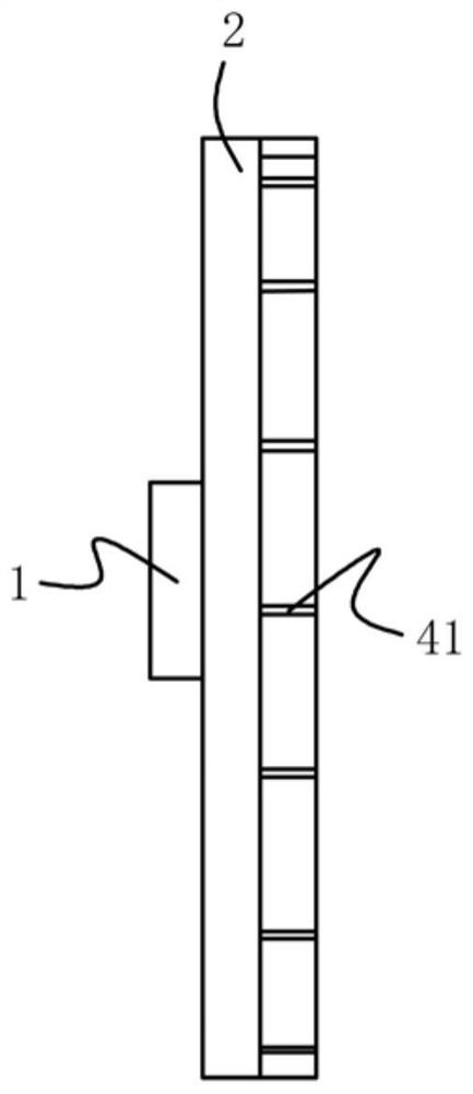
[0026] Embodiment one, such as Figure 1-2 As shown, a device for installing a radio frequency chip in an anti-theft device includes a mechanical arm and an installation component arranged at the front end of the mechanical arm. Wherein, the mounting assembly includes a connecting piece 1 fixed to the mechanical arm, and a mounting base 2 arranged under the connecting piece 1 .

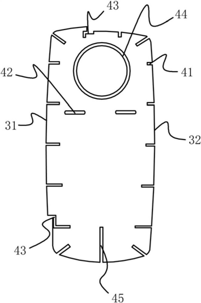
[0027] The bottom of the mounting base 2 is provided with a slot through the bottom surface. The side of the mounting base 2 includes a first outer edge 31 and a second outer edge 32 . The first outer edge 31 protrudes from the second outer edge 32 .

[0028] Further, the mounting base 2 is provided with a built-in electromagnet at the second outer edge 32 .

[0029] Further, the mounting seat 2 is made of a magnetic material, and the electromagnet is semi-enclosed in the mounting seat 2 along the starting end of the second outer edge 32 to the terminal end of the second outer edge 32. The circuit o...

Embodiment 2

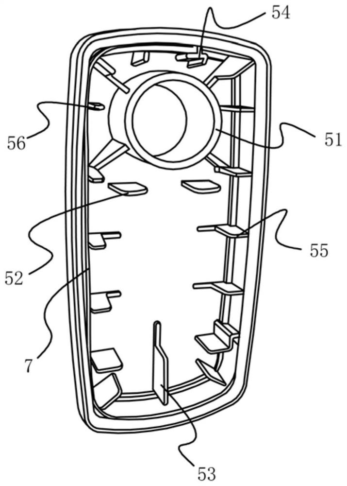
[0037] Embodiment two, such as Figure 3-4 As shown, an anti-theft device includes a base 5 , a top cover 6 , a chip strip 7 and a coil, the chip strip 7 and the coil are fixed in the base 5 , and the top cover 6 is set on the base 5 . Wherein, the chip strip 7 is fixed in the base 5 by the installation device in the first embodiment.

[0038] The inside of the base 5 is provided with an upper cover insertion ring 51 , a coil side support 52 , a coil bottom support 53 and a chip strip limit block 54 .

[0039] Among them, the upper cover insertion ring 51 can be inserted into the annular slot 44 of the installation assembly, the coil side support 52 can be inserted into the center positioning slot 42 of the installation assembly, and the coil bottom support 53 can be inserted into the bottom support slot 45 of the installation assembly. Inserting, the chip strip limiting block 54 can be inserted into the limiting slot 43 of the installation component.

[0040] The limit bloc...


PUM


Abstract

The invention discloses a mounting device of a radio frequency chip in an anti-theft device. The mounting device comprises a mechanical arm and a mounting assembly arranged at the front end of the mechanical arm, and is characterized in that the mounting assembly comprises a connecting piece fixed with the mechanical arm and a mounting seat arranged below the connecting piece, a slot penetrating through the bottom surface is formed in the lower part of the mounting seat; the side edge of the mounting seat comprises a first outer edge and a second outer edge, and the first outer edge protrudesout of the second outer edge; and a built-in electromagnet is arranged at the second outer edge of the mounting seat. The radio frequency chip is attracted or put down through on-off of the electromagnet, the radio frequency chip can be accurately attracted and placed due to the fact that the first outer edge protrudes out of the second outer edge, the purpose of changing people through a machineis achieved, the production efficiency is high, installation is accurate, and the radio frequency chip is not prone to being broken.

Description

technical field [0001] The invention belongs to the technical field of anti-theft devices, and in particular relates to a radio frequency chip installation device in the anti-theft device and the anti-theft device. Background technique [0002] In shopping malls, supermarkets, clothing stores and other stores, clothing anti-theft buckles are usually used for anti-theft processing. The existing anti-theft buckles adopt a built-in radio frequency chip and set an induction door at the door of the store for anti-theft. [0003] Conventional anti-theft buckle, such as the technical scheme disclosed in Chinese patent CN105405243A, is a radio frequency identification buzzer anti-theft buckle for clothing. Electronic label, button battery, buzzer, described radio frequency electronic label is connected with described button battery, described buzzer respectively, has ink box in described anti-theft buckle housing, and described ink box is equipped with ink. [0004] Similar to the...

Claims


Application Information

Patent Timeline
Patent Type & Authority Applications(China)
IPC IPC(8): G08B13/24
CPCG08B13/2417G08B13/2434
Inventor 金军勇
Owner 深圳市华辰信科电子有限公司
Why Eureka
Try Eureka