
Oil-resistant drag chain line and production process

A drag chain line, oil-resistant technology, applied in strip/foil conductors, bendable conductors, cable/conductor manufacturing, etc., can solve the problem of broken or cracked outer sheath of insulated conductors, twisted wires and insulation damage, Problems such as short circuit or broken skin can be achieved to reduce the work intensity of the assembly process, resist various acid and alkali chemical reagents, and eliminate the risk of short circuit of wires

Inactive Publication Date: 2021-02-19
乐庭电线工业(常州)有限公司 +2
View PDF4 Cites 2 Cited by
  • Summary
  • Abstract
  • Description
  • Claims
  • Application Information

AI Technical Summary

Problems solved by technology

[0008] Since the assembly is a separate finished line, the length of the cutting line is often improper, unequal or mismatched, and the wiring is not neat and smooth, resulting in different actual lengths of each type of wire in the cable trough. Risk of wire breakage due to force imbalance
[0009] After the traditional towline wire is bent many times in the towline, the insulated conductor, insulating compound, shielding layer conductor, and outer sheath layer are often broken or cracked. The broken conductor will cause the wire to break, and the cracked insulation layer will cause a short circuit. Faults such as burning chips and cracking of the sheath layer will cause leakage risks. For traditional towline cables with unreasonable layout, wire twisting and insulation damage will occur frequently. The twisting and damage points are prone to open circuit, short circuit or broken skin.

Method used

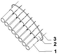

Image

  • Oil-resistant drag chain line and production process
  • Oil-resistant drag chain line and production process

Examples


Embodiment 1

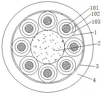
[0032] see figure 2 , an oil-resistant drag chain line, including several core wire layers 1, and several of the core wire layers 1 include a Kevlar inner layer 101, a conductor 102 and an insulating layer 103, and the Kevlar inner layer 101 is arranged on the conductor 102 In the center, the conductor 102 is tightly wrapped on the outer layer of the inner layer 101 of the Kevlar wire, and the insulating layer 103 is tightly wrapped on the outside of the conductor 102. Several core wire layers 1 are arranged in a circle, and several core wire layers 1 are arranged in a circle. The center of the arrangement is equipped with a central layer 2 of Kevlar wires, and the outside of several core wire layers 1 is tightly covered with an outer coating layer 4 .

[0033] A fastening layer 3 is also arranged between the core wire layers 1 and the outer covering layer 4, the inner wall of the fastening layer 3 is tightly wrapped on the outside of several core wire layers 1, and the outsi...


PUM

PropertyMeasurementUnit
tensile strengthaaaaaaaaaa
elongationaaaaaaaaaa

Abstract

The invention discloses an oil-resistant drag chain wire, and the wire comprises a plurality of core wire layers; each core wire layer comprises a Kevlar wire inner layer, a conductor and an insulating layer; the Kevlar wire inner layer is arranged in the center of the conductor, the conductor is tightly coated on the outer surface layer of the Kevlar wire inner layer, and the insulating layer istightly coated on the outer side of the conductor. The plurality of core wire layers are annularly arranged, a Kevlar wire central layer is arranged in the center of the annular arrangement of the plurality of core wire layers, and the outer sides of the plurality of core wire layers are tightly coated with an outer coating layer; according to the drag chain wire, a plurality of machine tool corewires in the prior art are directly compounded into one wire and separated through the insulating layer, only one wire harness needs to be fixed in a machine tool, and the problems that due to the fact that multiple existing machine tool wire harnesses need to be tightly bound together, a cable insulating layer is often damaged to a certain extent due to tight binding, and equipment often operatesin an overload mode, the cable is scrapped in advance due to excessive use or bad use when the cable does not reach the expected service life value is solved.

Description

technical field [0001] The invention belongs to the technical field of cables for machine tools, and in particular relates to an oil-resistant drag chain cable and a production process. Background technique [0002] The towline cable is a highly flexible special cable that can move back and forth with the towline and is not easy to wear. It can also be called a tank chain cable, which is gradually developed from the machine tool cable. Early towline cables were put together by a number of wires of different specifications, fixed by a tightening device and then arranged in a cable trough for use (after tightening, some network pipes will be added to the outermost layer to improve wear resistance). The conductors are multiple tinned annealed annealed copper wires, and the insulating compound is made of polyvinyl chloride. Due to the limitation of the old-fashioned tightening device, the cable insulation layer is often damaged to a certain extent during tightening, and the equ...

Claims


Application Information

Patent Timeline
Patent Type & Authority Applications(China)
IPC IPC(8): H01B7/00H01B7/02H01B7/04H01B7/17H01B7/18H01B7/28H01B3/44H01B13/00
CPCH01B3/445H01B7/0018H01B7/0045H01B7/0275H01B7/041H01B7/17H01B7/1825H01B7/187H01B7/1875H01B7/28H01B13/00Y02A30/14
Inventor 赵航张惠娟安富涛教明章
Owner 乐庭电线工业(常州)有限公司
Learn More