Building construction dust removal device

A technology for dust removal device and building construction, which is applied to the separation of dispersed particles, chemical instruments and methods, and the use of liquid separators, etc., can solve the problems of inability to further improve the dust removal effect of the device, reduce the range of dust removal, and affect the range of dust removal by the device, etc. To achieve the effect of increasing the range of sprayed water mist and improving the dust removal efficiency

Inactive Publication Date: 2021-02-23
云南建丰实业(集团)有限公司
View PDF3 Cites 5 Cited by
  • Summary
  • Abstract
  • Description
  • Claims
  • Application Information

AI Technical Summary

Problems solved by technology

[0003] The current construction dust removal device usually sprays directly through the spray gun barrel, so that the dust in the air falls to the ground, and the spray direction is relatively fixed. It is very inconvenient to adjust the horizontal angle manually when adjusting, and it also affects the dust removal range of the device; and the current When the construction dust removal device adjusts the inclination angle of the spray barrel, it usually needs to be adjusted manually. The direction in which the adjusted spray barrel can spray water mist is also relatively fixed, and it is impossible to control the horizontal rotation of the spray barrel. At the same time, the spray gun barrel is controlled to automatically adjust the tilt angle, which greatly reduces the dust removal range of the whole device on the construction site, and also reduces the use effect of the device; at the same time, the current construction dust removal device only removes dust by spraying water mist , the dust removal method is single, and the dust removal effect of the device cannot be further improved

Method used


Image

  • Building construction dust removal device
  • Building construction dust removal device
  • Building construction dust removal device

Examples


Embodiment 1

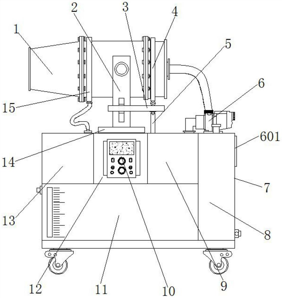
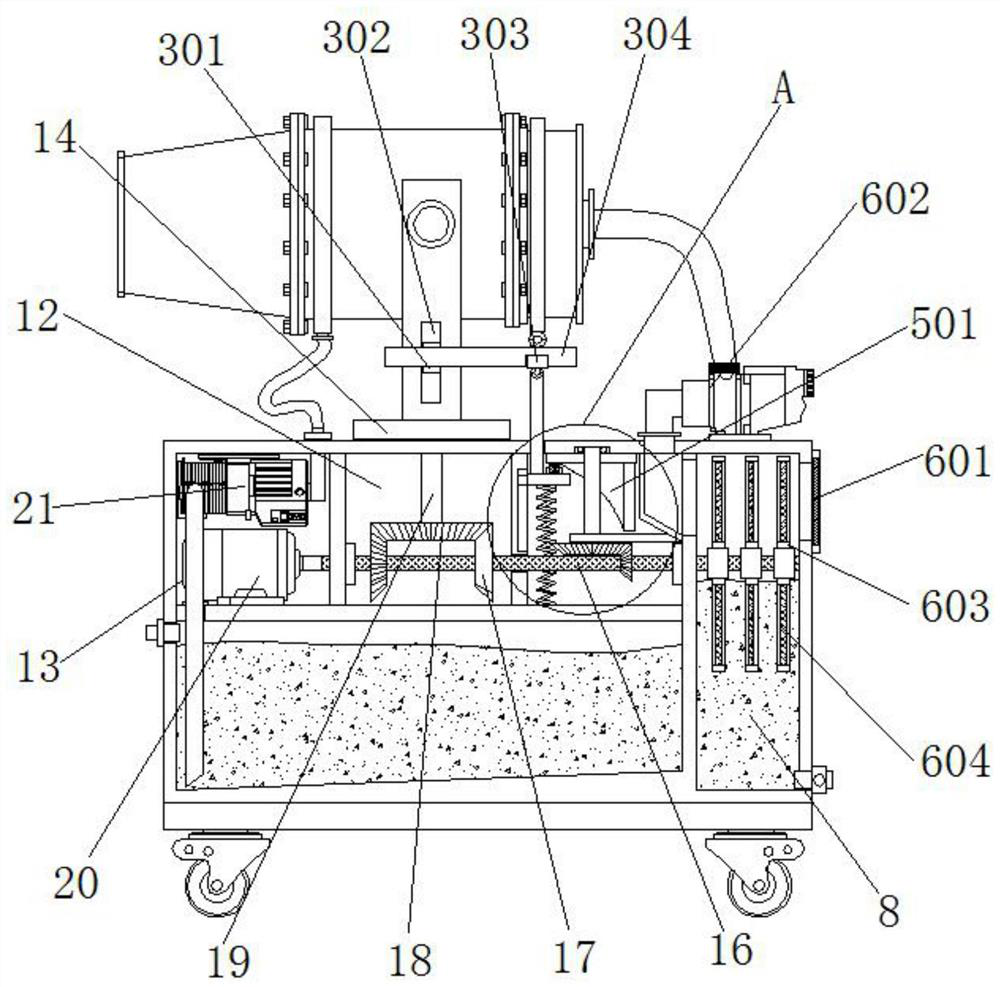
[0036] Example 1, such as figure 1 , 2 As shown in and 4, when the spraying gun barrel 1 is required to swing back and forth horizontally, the driving motor 20 is used to drive the driving shaft 16 to rotate, and the driving shaft 16 drives two groups of first bevel gears 17 to rotate, and the first group of first bevel gears 17 meshes with the second bevel gear 18 to drive the rotating rod 19 and the rotating disk 14 to rotate clockwise, the first bevel gear 17 of the second group does not mesh with the second bevel gear 18, and the first bevel gear 17 of the second group When meshing with the second bevel gear 18, it will drive the rotating rod 19 and the turntable 14 to rotate counterclockwise, thereby driving the U-shaped frame 2 and the spraying barrel 1 to swing back and forth horizontally, so that the sprayed out of the spraying barrel 1 The water mist can be sprayed in different horizontal directions to improve the spraying range of the water mist.

Embodiment 2

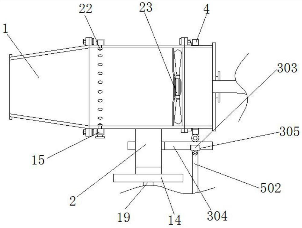
[0037] Example 2, such as figure 1 , 2 , 3, 5, 7 and 8, when the spray gun barrel 1 needs to be continuously changed in the process of swinging back and forth in the level, the drive shaft 16 is used to drive the small bevel gear 506 to rotate, and the small bevel gear 506 passes through and The large bevel gear 507 cooperates to drive the rotation shaft 504 to rotate, thereby driving the adjustment ring 501 to rotate. During the rotation of the adjustment ring 501, the cooperation between the adjustment ring 501 and the roller 503 is used to force the lifting plate 505 to continuously rise and fall, and the spring 508 is continuously shortened. Re-extended again, lifting plate 505 lifts and lifts connecting rod 502 to lift, and utilizes connecting rod 502 to pull U-shaped plate 304 to lift, thereby pulling the end of spray gun barrel 1 close to dust filter chamber 8 through collar 4 and gradually tilting downward. The collar 4 gradually slides on the outside of the spray bar...

Embodiment 3

[0038] Example 3, such as figure 1 , 2 As shown in and 6, before the outside air enters the inside of the spray gun barrel 1, the outside air first passes through multiple sets of rotating filter screens 604, and the dust in the air is filtered and blocked by the water-soaked filter screen 604 and the dust is adsorbed on the surface of the filter screen 604 , and when the dust-attached part of the filter screen 604 enters the clean water inside the dust filter chamber 8 due to rotation, the attached dust will fall off into the clean water again, and the rotating filter screen 604 is constantly used to filter the air entering the spray gun barrel 1. Purification treatment in advance, combined with the sprayed water mist inside the spray gun barrel 1, can greatly improve the dust removal effect of the device.

[0039] Working principle: Connect the device to the power supply before use, then use the universal wheels to move the device to the designated position, and then turn o...


PUM


Abstract

The invention discloses a building construction dust removal device which comprises a main body bin, a dust filtering bin is arranged at one end of the bottom in the main body bin, a water storage binis arranged at the other end of the bottom in the main body bin, and a second mounting bin is arranged in the middle of the top of the water storage bin; and a third mounting bin and a first mountingbin are arranged at the two ends of the top of the water storage bin correspondingly, a driving motor is mounted at the inner bottom of the third mounting bin, a driving shaft is mounted at the output end of the driving motor, and the driving shaft sequentially penetrates through the second mounting bin, the first mounting bin and the dust filtering bin. Through cooperative use of the spraying gun barrel, the U-shaped frame, the lifting assembly, the first mounting bin, the driving shaft and the driving motor, the inclination angle of the spraying gun barrel can be continuously changed in thehorizontal back-and-forth swinging process of the spraying gun barrel, so that the water mist spraying range of the whole device is greatly enlarged, and the dust removal efficiency of the device isalso improved; and popularization and application of the device are facilitated.

Description

technical field [0001] The invention relates to the technical field of construction dust removal, in particular to a construction dust removal device. Background technique [0002] Flying dust pollution in construction refers to the air pollution caused by dust particles produced in production activities such as house construction, road and pipeline construction, house demolition, material transportation, material stacking, road cleaning, and mud exposure. Residential areas and other surrounding areas where a large number of people live have seriously affected the lives of residents. In order to prevent dust pollution, protect and improve the quality of the air environment, dust removal devices are usually used to reduce flying dust at the construction site. [0003] The current construction dust removal device usually sprays directly through the spray gun barrel, so that the dust in the air falls to the ground, and the spray direction is relatively fixed. It is very inconve...

Claims


Application Information

Patent Timeline
Patent Type & Authority Applications(China)
IPC IPC(8): B01D47/08B01D47/02
CPCB01D47/028B01D47/08
Inventor 不公告发明人
Owner 云南建丰实业(集团)有限公司
Why Eureka
Try Eureka