Noctilucent ultrafine particle heating and stirring equipment for noctilucent textiles

A technology of ultra-fine particles, heating and stirring, applied in heat treatment, chemical/physical/physicochemical fixed reactors, melting, etc., can solve the problems of small application range, poisonous and harmful, environmental pollution, etc., to improve the stirring effect, improve Practicality and the effect of improving work efficiency

Pending Publication Date: 2021-02-23
SUZHOU HUIYING TEXTILE TECH CO LTD
View PDF3 Cites 0 Cited by
  • Summary
  • Abstract
  • Description
  • Claims
  • Application Information

AI Technical Summary

Problems solved by technology

[0002] Luminous ultrafine particles, also known as fluorescent powder (commonly known as luminous powder), also called calcium fluoride, are usually divided into two types: photoluminescent powder with energy storage and radioactive luminous powder. After being irradiated by natural light, daylight, ultraviolet light, etc., the light energy is stored, and after the light is stopped, it is slowly released in the form of fluorescence, so at night or in the dark, the luminescence can still be seen and lasts for a long time For several hours to more than ten hours, the radioactive luminous powder is mixed with radioactive substances in the fluorescent powder, and the rays emitted by the radioactive substances are used to stimulate the fluorescent powder to emit light. This kind of luminous powder has a long glow time, but it is poisonous and harmful. Will cause environmental pollution, etc., so the application range is small

Method used


Image

  • Noctilucent ultrafine particle heating and stirring equipment for noctilucent textiles
  • Noctilucent ultrafine particle heating and stirring equipment for noctilucent textiles
  • Noctilucent ultrafine particle heating and stirring equipment for noctilucent textiles

Examples


Embodiment 1

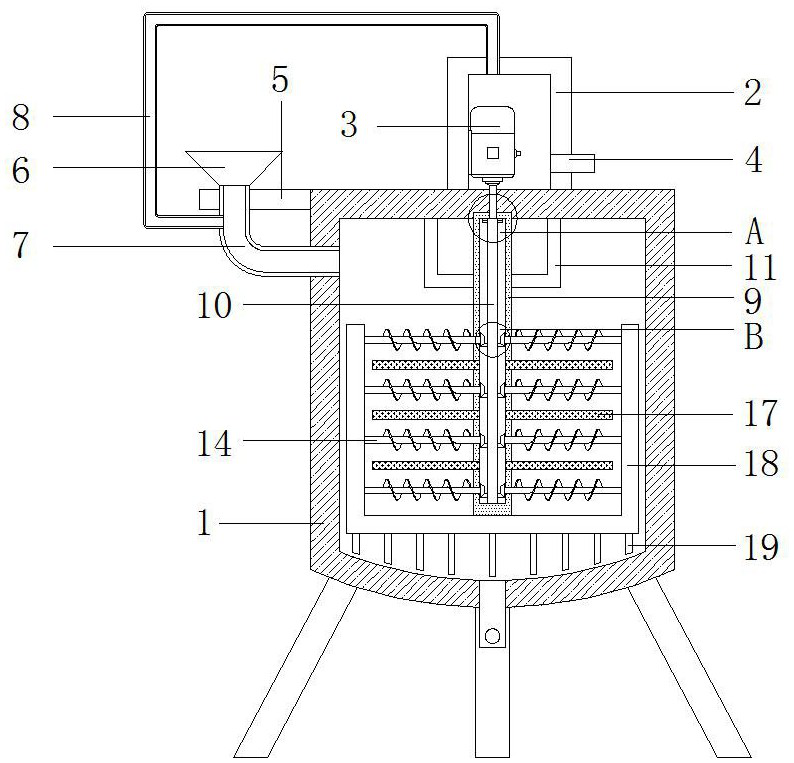
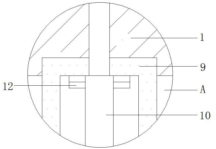
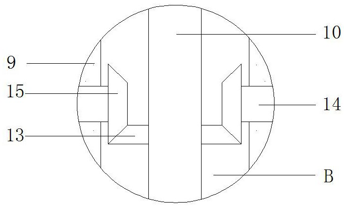
[0023] Embodiment 1, with reference to Figure 1-5 , a kind of heating and stirring equipment for luminous ultrafine particles for luminous textiles, comprising a thermal insulation shell 1, the outer walls of the four corners of the bottom of the thermal insulation shell 1 are welded with supporting legs, and the outer walls of the bottom ends of the four supporting legs are fixedly connected with An anti-skid pad, an installation box 2 is welded on the top outer wall of the thermal insulation shell 1, and a motor 3 is connected to the inner wall of one side of the installation box 2 by bolts, and an air inlet is opened on the inner wall of the installation box 2 away from the motor 3 A one-way air intake valve 4 is socketed on the inner wall of the air inlet, a connecting plate 5 is welded on the outer wall of one side of the heat preservation shell 1, and a feeding hopper 6 is socketed on the outer wall of one end of the top of the connecting plate 5, A feeding pipe 7 is so...


PUM


Abstract

The invention discloses noctilucent ultrafine particle heating and stirring equipment for noctilucent textiles. The equipment comprises a heat preservation shell, a mounting box is welded to the outerwall of the top of the heat preservation shell, a motor is connected to the inner wall of one side of the mounting box through bolts, a connecting plate is welded to the outer wall of one side of theheat preservation shell, the outer wall of one end of the top of the connecting plate is sleeved with a feeding hopper, the inner wall of the bottom end of the feeding hopper is sleeved with a feeding pipe, one end of the feeding pipe communicates with the interior of the heat preservation shell, the inner wall of one end of the top of the mounting box is sleeved with a supporting air conveying pipe, and one end of the supporting air conveying pipe communicates with the interior of the feeding pipe. By means of the sleeve, the transmission shaft and the spiral blades, the stirring effect is improved, noctilucent ultrafine particles can be heated evenly, stirring and heating can be conducted at the same time, the working efficiency is improved, heat generated by the motor is used for preheating the noctilucent ultrafine particles in the feeding pipe, and meanwhile the noctilucent ultrafine particles can be assisted in entering the heat preservation shell and improving practicality.

Description

technical field [0001] The invention relates to the technical field of luminous ultrafine particles, in particular to a heating and stirring device for luminous ultrafine particles used in luminous textiles. Background technique [0002] Luminous ultrafine particles, also known as fluorescent powder (commonly known as luminous powder), also called calcium fluoride, are usually divided into two types: photoluminescent powder with energy storage and radioactive luminous powder. After being irradiated by natural light, daylight, ultraviolet light, etc., the light energy is stored, and after the light is stopped, it is slowly released in the form of fluorescence, so at night or in the dark, the luminescence can still be seen and lasts for a long time For several hours to more than ten hours, the radioactive luminous powder is mixed with radioactive substances in the fluorescent powder, and the rays emitted by the radioactive substances are used to stimulate the fluorescent powde...

Claims


Application Information

Patent Timeline
IPC IPC(8): B01J6/00B01J19/18B01J19/20
CPCB01J6/005B01J19/18B01J19/20B01J19/0066B01J19/0053B01J2219/00135B01J2219/00123B01J2219/0015
Inventor 谭文丽
Owner SUZHOU HUIYING TEXTILE TECH CO LTD
Why Eureka
Try Eureka