Non-stop edge grinding equipment for protrusions in surface grooves for metal product production

A technology for metal products and edging equipment, applied in metal processing equipment, grinding/polishing equipment, other manufacturing equipment/tools, etc., can solve the problems of reducing equipment service life, complicated operation, etc., to reduce the difficulty of operation and avoid repeated Stop to check the progress of processing and protect the effect of edge grinding equipment

Active Publication Date: 2021-02-23
上海弘智金属制品有限公司
11 Cites 0 Cited by

AI-Extracted Technical Summary

Problems solved by technology

[0003] After the production of metal products, it is necessary to polish the bumps that cause uneven surfaces during processing. However, some bumps with a certain volume and located in the grooves on the surface of the metal product body are difficult to cut effectively by cutting equipment. Generally, it is processed by edging equipment, but in the processing process, in order to avoid excessive damage to the metal...

Method used

The diameter of drill portion 307 is equal to the distance between contact block 210 and contact sensor 211 in the initial state, which is used to realize that contact block 210 is abutted against contact sensor 211 after edging structure has completely processed raised block 101 , the feedback signal controls the drivi...

Abstract

The invention discloses non-stop edge grinding equipment for protrusions in surface grooves for metal product production, and belongs to the technical field of metal product production. The non-stop edge grinding equipment comprises a metal product body, a sensing edge grinding assembly and a pretreatment assembly, wherein a groove is formed in the surface of the metal product body, and a protruding block is arranged in the groove; a bidirectional sliding rail is arranged on the surface of a mounting base table; and the pretreatment assembly comprises a base, and the base is fixedly connectedwith the mounting base table. The bottom of the joint of the protruding block and the metal product body is slotted in advance through a drill bit part arranged in the side direction of the protrudingblock, then the protruding block is treated from top to bottom through an edge grinding structure, and along with continuous operation of the edge grinding structure, a connecting rod moves upwards along a guide frame till a contact block abuts against a contact sensor, a feedback signal controls a driving motor to stop working, so that the treatment of the protruding block in the groove is completed, the treatment operation is carried out at one time, the repeated shutdown for checking the treatment progress is avoided, the operation difficulty is reduced, and the edge grinding equipment isprotected.

Application Domain

Edge grinding machinesOther manufacturing equipments/tools

Technology Topic

GrindingElectric machinery +6

Image

  • Non-stop edge grinding equipment for protrusions in surface grooves for metal product production
  • Non-stop edge grinding equipment for protrusions in surface grooves for metal product production
  • Non-stop edge grinding equipment for protrusions in surface grooves for metal product production

Examples

  • Experimental program(1)

Example Embodiment

[0026] The technical solutions in the embodiments of the present invention will be clearly and completely described below with reference to the accompanying drawings in the embodiments of the present invention. Obviously, the described embodiments are only a part of the embodiments of the present invention, rather than all the embodiments. Based on the embodiments in the present invention, all other embodiments obtained by those of ordinary skill in the art without creative work, all belong to the protection scope of the present invention.
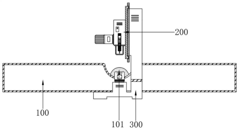
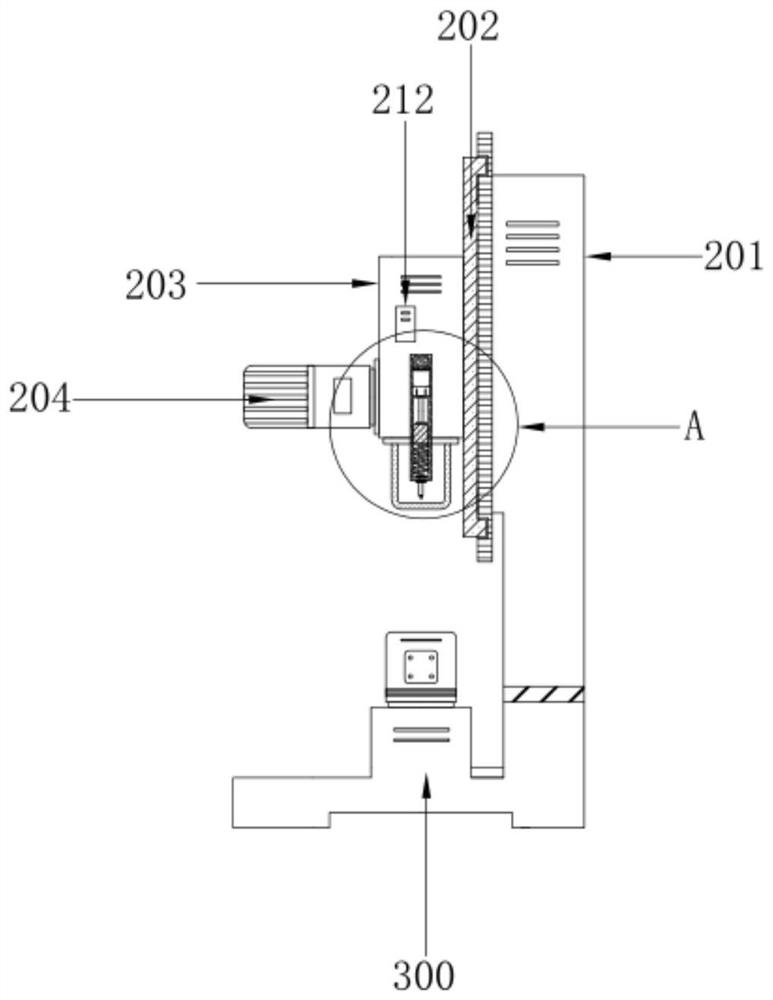
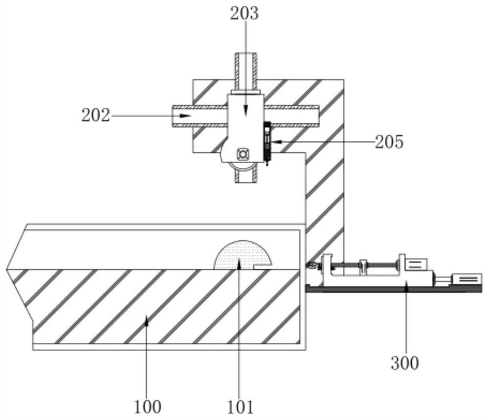
[0027] see figure 1 , the present invention provides a non-stop edging equipment for the production of metal products with protrusions in surface grooves, comprising: a metal product body 100, a groove is formed on the surface of the metal product body 100, and a convex block 101 is arranged in the groove; The edging assembly 200 includes an installation base 201, the surface of the installation base 201 is provided with a bidirectional sliding rail 202, a protective shell 203 is movably provided on the bidirectional sliding rail 202, and an edging structure is provided in the protective shell 203 (not marked in the figure, That is, the grinding disc in the prior art), and the outer wall of the protective shell 203 is provided with a drive motor 204; the pretreatment assembly 300, the pretreatment assembly 300 includes a base 301, the base 301 is fixedly connected with the installation base 201, and the base 301 is set on a metal The product body 100 is close to one end of the protruding block 101 .
[0028] see Figure 2-4 The outer wall of the protective shell 203 is vertically fixed with a guide frame 205, the bottom of the guide frame 205 is movably inserted with a connecting rod 206, the bottom end of the connecting rod 206 is provided with an induction head 209, and the top of the connecting rod 206 is fixedly connected with a contact block 210, through The edging structure processes the raised block 101 from top to bottom. During the processing, the induction head 209 is always attached to the surface of the raised block 101. When the bottom edge of the edging structure is processed to the pre-opened groove, the connecting rod drives the induction The head 209 comes into contact with the introduction piece 403 in advance under the action of the return spring 208 .
[0029] see Figure 2-4 , the guide frame 205 is provided with a middle block 207, the connecting rod 206 is arranged movably through the middle block 207, and the connecting rod 206 is close to the body of the induction head 209 with a return spring 208, and the induction head 209 is embedded with a surface. The rubber head structure of the sensor.
[0030] see Figure 2-4 , the contact block 210 is slidably connected with the inner wall of the guide frame 205, the inner wall of the guide frame 205 is provided with a chute, and the top of the inner cavity of the guide frame 205 is provided with a contact sensor 211, the output end of the contact sensor 211 is electrically connected with the controller 212, the controller The output end of the 212 is electrically connected to the drive motor 204. With the continuous operation of the edging structure, the connecting rod 206 moves upward along the guide frame 205 until the contact block 210 is in contact with the contact sensor 211. At this time, the edging structure bottoms The edge just abuts the raised block 101 and the surface of the metal product body 100, the feedback signal controls the drive motor 204 to stop working, completes the processing of the raised block 101 in the groove, and performs the processing operation at one time, avoiding repeated shutdowns for inspection and processing. The progress is reduced, the operation difficulty is reduced, and the edging equipment is protected.
[0031] see image 3 and Figure 5 The top surface of the base 301 is provided with a processing table 302 that moves left and right. The processing table 302 is moved laterally on the processing table 302 by pushing the cylinder 303, and a groove is pre-opened on the raised block 101 to partially separate the raised block 101 from the metal. In the product body 100, a groove is formed on the top surface of the processing table 302, a support block 304 is formed in the groove, and a shaft hole with a bearing embedded therein is formed on the support block 304.
[0032] see image 3 and Figure 5 The support block 304 is provided with a rotating shaft 305, one end of the rotating shaft 305 is connected with the output end of the stepping motor 306, and the other end of the rotating shaft 305 penetrates the processing table 302 and is connected with the drill head 307, and is driven to rotate by the stepping motor 306 The shaft 305 is rotated, and the bottom of the protruding block 101 is pre-grooved. The length of the drill head 307 is greater than the horizontal distance between the center of the protective shell 203 and the center of the guide frame 205 .
[0033] see Figure 4 and Figure 5, a detection assembly 400 is provided on the processing table 302 and below the drill head 307 , the detection assembly 400 includes a pipe body 401 inserted on the processing table 302 , the inner cavity of the pipe body 401 is provided with a push rod 402 , and the end of the push rod 402 is fixed Connecting the introduction piece 403, the end of the pipe body 401 facing the drill head 307 is an open structure.
[0034] see Figure 4 and Figure 5 , the introduction piece 403 has an arc-shaped piece structure, and the surface of the introduction piece 403 is evenly provided with induction points, and the bottom of the connection between the introduction piece 403 and the metal product body 100 is pre-grooved through the drill head 307 arranged laterally on the raised block 101. , the groove separates the protruding block 101 from the surface of the metal product body 100, and pushes the lead-in piece 403 into the groove. Made of aluminum alloy material.
[0035] The diameter of the drill head 307 is equal to the distance between the contact block 210 and the contact sensor 211 when the contact block 210 is in the initial state, which is used to realize that after the edging structure completely processes the convex block 101, the contact block 210 is in contact with the contact sensor 211, and a feedback signal is obtained. Control the drive motor 204 to stop working, complete the processing of the raised block 101 in the groove, and perform the processing operation at one time, avoiding repeated shutdowns to check the processing progress, and the drill head 307 is located directly below the induction head 209 during operation.
[0036] The standard parts used in the present invention can be purchased from the market, the special-shaped parts can be customized according to the description in the specification and the drawings, and the specific connection methods of each part adopt mature bolts, rivets, welding, etc. in the prior art Conventional means, machinery, parts and equipment all use conventional models in the prior art, and circuit connections adopt conventional connection methods in the prior art, which will not be described in detail here.
[0037] Although embodiments of the present invention have been shown and described, it will be understood by those skilled in the art that various changes, modifications, and substitutions can be made in these embodiments without departing from the principle and spirit of the invention and modifications, the scope of the invention is defined by the appended claims and their equivalents.

PUM

no PUM

Description & Claims & Application Information

We can also present the details of the Description, Claims and Application information to help users get a comprehensive understanding of the technical details of the patent, such as background art, summary of invention, brief description of drawings, description of embodiments, and other original content. On the other hand, users can also determine the specific scope of protection of the technology through the list of claims; as well as understand the changes in the life cycle of the technology with the presentation of the patent timeline. Login to view more.

Similar technology patents

Pomegranate yield increasing planting method

Owner:蚌埠市金牛湾农业科技发展有限公司

Embedded rail replacing method

Owner:CHENGDU XINZHU ROAD & BRIDGE MASCH CO LTD

Classification and recommendation of technical efficacy words

Why Eureka
Try Eureka